|
Decibel Dungeon
|
|
You can see some pictures of my CD723 modifications HERE.
|
|
It's now a couple of months since I converted my Philips CD723 to a top-loader and I can confirm that that modification has made a considerable improvement. So much so, that I have not been inclined to do anything else to it - until now.
|
|
However, an article by Chris Found in the newsletter of the 'London Live Hi-Fi Circle' about improving the CD723's electronics has encouraged me to see how much more I can improve this humble CD player. Chris has kindly agreed to let me write up details of his modifications here on Decibel Dungeon. He will be publishing further modifications in due course which will appear here also.
|
|
Of course, you don't have to do both the top-loader conversion and the modifications to the electronics although I would suggest that if you are serious about having a top-end CD player, both are equally as important.
|
|
WARNING - The Philips CD723 is a budget priced CD player. One of the cost-cutting results of this design is fairly fragile PCB's. In fairness to Philips, they were designed to be populated with components and soldered only once. In the event of a repair being required it is usual to replace the whole board rather than try to replace the individual component(s). With this in mind, be very careful not to damage the PCBs. Remember that their tracks are VERY delicate and can be easily damaged. I managed to lift a track simply by applying a solder pump to the board so be warned.
|
| Site menu
Page menu
|
|
|
If you have not already got one, I strongly recommend that you get hold of a service manual for the CD723 from:
Willow Vale Electronics Limited
Connect Business Park
Bordesley Green Road
Birmingham
B9 4UA
England
Tel: 0870-6000-271
E-mail Willow Vale
Or click HERE for their web site.
Apparently, Willow Vale have not been contactable recently so I am indebted to Mike Mears for locating another source, namely Dutch West Distributions, tel - 01434 32 32 32. The manual appears to be slightly cheaper from them.
|
|
NOTE, if you have converted your CD723 to a top-loader then some of the details for 'getting started' may differ from those for the standard model given below. I'm assuming that if you have done the top-loader conversion, then you will already know how to access the various parts which are to be modified.
|
|
You will need a T10 screwdriver for most of the disassembly work on the CD723 which consists of the following steps:
Opening the case
Remove the seven T10 screws which secure the lid to the rest of the casing and remove the lid. Remember to have a suitable container to keep all the screws and other small parts in so that you don't lose any.Removing the CD board
- Disconnect the wire coming from the transport PCB to the chassis, the ribbon cables between the transport PCB and the power supply PCB.
- Remove the two screws securing the whole transport assembly to the chassis and carefully remove it from the case.
Make a note of their relative position as you will need to make sure that they are reassembled correctly.
- Remove the single screw which secures the PCB to the transport mechanism and remove the PCB by unclipping it.
Removing the AF board
- Disconnect the cable from the transformer to the power supply PCB.
- Remove the screws securing the digital and phono sockets of the AF board to the rear of the case and the one securing it to the base.
- Disconnect the cables which connect the PCB to the control panel PCB and the headphone PCB. You can now remove the AF PCB from the case.
|
| Site menu
Page menu
|
|
|
|
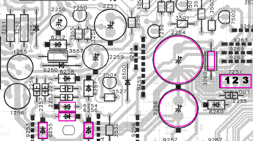
CD723 PSU Circuit with items to be modified highlighted (viewed from component side).
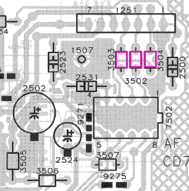
CD723 DAC Circuit (viewed from component side).
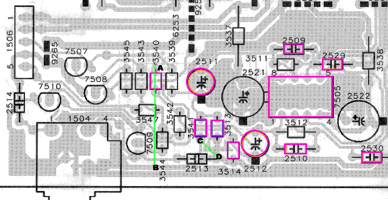
CD723 audio output circuit (viewed from component side).
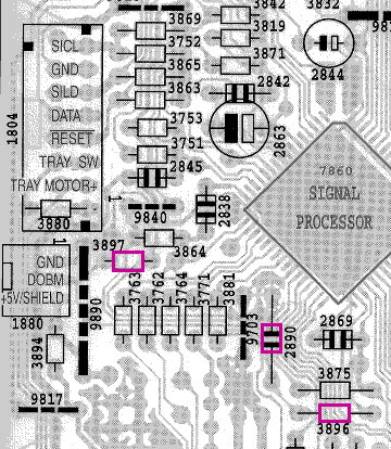
A section of the CD723 transport circuit (viewed from component side).
| | | |
|---|
|
WARNING - Be very careful handling the transport and its PCB. Be careful not to damage the delicate connector between the laser transport and the PCB. Also remember that the tracks on the PCB are VERY delicate and can be easily damaged.
|
|
There are many modifications which can be made to improve the performance of the CD transport section. At present we will concentrate on just one.
|
|
- Remove capacitor 2890 by either snipping it out or de-soldering.
- Remove the resistor 3896 and replace it with a wire link (or just short the terminals).
- Remove resistor 3897 by either snipping it out or de-soldering.
These modifications clean up the waveform which is output by the transport.
|
|
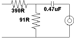 It has been suggested to me that a better arrangement on the controller board may be:
-
Change R3896 to 390R
-
Change R3897 to 91R
-
Remove C2890
|
|
|
|
|
|
If you are going to be using the CD723 as a transport, then it will benefit you to modify the digital output from the transport as follows:
On the AF board:
- Change C2541 to 0.47uF (probably not necessary)
-
Remove transformer 5801 and fit links on the pcb between pins 3 & 4 and 1 & 6
-
Replace R3556 with a link
-
Remove C2543
|
| Site menu
Page menu
|
|
|
|
|
The performance of the audio stage can be improved further by reducing the DC offset of the integrating opamp which can be done in two ways:
- The simple way to provide an inverted DC voltage to the negative voltage input of the opamp and grounding the positive signal terminal. This allows fine offset control but eventually drifts.
Unfortunately, Chris Found will not now be supplying further mods for the CD723 but if anybody has any mods for this CD player, I will be happy to describe them on these pages. You may also find the following two links of interest:
PDF document on the "VAM 1201 + Short Loader MKIII"(See page 10).
Technical description of Short Loader.
|
|
Thorsten Loetch has kindly provoded a bit more information on possible mods to the CD723.
|
|
Thorsten did a lot of work on the 721, which shares a lot of things with the 723.
The key changes he made apart from reinforcing the chassis:
- 1) New Clock (Tricord?)
- 2) Analogue Stage with LM6182 and a DC offset circuit to allow direct coupled outputs. For this the feedback loop capacitor and the LC circuit were removed. The Lowpass was realised AFTER the LM6182 100 ohm Output Resistor with 22nF to ground.
- 3) 120VA torroidal Transformer plus Schottky Diodes, low Z Electrolytics supply regulated via LM317/337 supplying +/-15V for the Analogue Stage, good local decoupling for the Analogue Stage. A seperate 5V supply tapped off the +15V for the TDA1545 DAC.
|
|
T also has a cute little valve based analogue stage for the TDA1545 (it needs to be modified for 2mA full scale current though - 2 resistors changed - see datasheet), as attached. Click HERE to see the circuit diagram.
|
|
Please note, I do not have any further details on Thorsten's mods so please don't write and ask me any questions about them.
|
|
UPDATE
I have now done most of the modification on my own CD723. Even though one of my power amps is out of action and I am using a much inferior substitute at present, I can clearly hear the improvements in the sound. I have not fitted a replacement op amp as I will later be using a separate modified Cambridge DACMAGIC 2i.
|
|
The job is not too difficult although I can't stress how important it is to take your time and be careful not to damage the very delicate tracks on the PCBs. Unfortunately, many of the component leadouts have been bent tightly against the tracks and getting them loose is quite fiddly. I suggest snipping out the components to be replaced and then removing what is left of their leadouts.
|
|
Perhaps the biggest problem was to fit the two new 4700 ufd PSU caps with their bypass caps. In the end, in order to accomodate them under the transport PCB, I had to lie them horizontally and solder the bypass caps undeneath the PCB.
|
|
You can see some pictures of my CD723 modifications HERE.
|
|
Judging by the number of emails I get about modding the CD723, it must be one of the most popular CD players of all time. I'd be happy to report anybdy else's experiences with this player here on Decibel Dungeon.
|
| Site menu
Page menu
|
|
|
 It has been suggested to me that a better arrangement on the controller board may be: