|
Decibel Dungeon
|
|
|
|
These loudspeakers were conceived as partners for the Gainclone chip amplifiers that I had built. The idea was that the Gainclones, speakers and modified CD723 CD player would form a top-end hi-fi system for minimal outlay. And the only way to find out if that was possible was to try and do it! Of course, there is no reason why these speakers cannot be used with other amplifiers. Indeed, they will offer a very easy load to any amplifier.
|
|
I set a very tight budget of around 50 UKP and knew that for that sort of money, I would need to keep things ultra simple. That led to the idea of a full-range driver with no crossover components to bump up the cost. And to try and be different, and not build just another pair of boxes, I decided to go with an open baffle arrangement.
|
|
A couple of years previously, I had built a lovely sounding pair of speakers using polystyrene sheet and decided to use it again and see how it would work with this design. Polystyrene is actually very easy to work with and as I wanted to make this design as easy for others to copy, it seemed like a good idea to use something that didn't require the usual woodworking skills or equipment.
|
|
Finally, just to bring in another idea that I have that is a little different to conventional loudspeaker design, I decided to build these speakers using a 'skeleton' covered with a 'skin', rather than the usual 'box' design. This would be especially useful as the panels of polystyrene do not have the strength of other materials like timber although my previous attempt at a ported design was surprisingly rugged! However, in that case I used 50mm thick polystyrene and for this ultra-cheapo design, I had chosen 25mm thickness for the side panels!
|
|
From the outset, I realized that there would have to be some compromises, but that's true of nearly any speaker system! Open baffles are renowned for their clarity, but not the amount of bass that they produce. Full-range drivers gain from not having a crossover between them and the power amps so there are no phase shifts or other 'manipulations' of the signal. They produce very good transients but without any crossover, there is nothing to control the response so it probably won't be 'textbook smooth'. Anyway, I like a challenge and providing it doesn't cost too much, I don't mind trying something for myself, rather than rely on the experiences of others so the project was started with the ordering of the drivers.
|
|
When I set out on a two year backpacking trip around the world in 1979, amongst the cards that I received wishing me 'bon voyage', one contained the following words that I have never forgotten:
Do not go where the path may lead.
Go, instead, where there is no path
and leave a trail.
|
|
|
|
After a lengthy search through the online catalogues that I could find on the internet (UK suppliers), the choice of drivers that came within budget were reduced to just two or three models. I have to say that I was most frustrated at not being able to get hold of the Small Thiele parameters for most of the drive units I looked at. What are these suppliers thinking of when the only details they provide are the size, weight and resistance of a drive unit! Come on guys, get real, we need this information!
|
|
After an unsuccessful attempt to get the TS parameters on any of the drivers I was interested in, I took a leap in the dark and ordered a pair of eight inch full-range units from CPC at a cost of just under 25 UKP. They come in two 'flavours', one with a whizzer cone and one without. I chose the whizzer cones knowing that I could cut them off if I didn't like them.
|
|
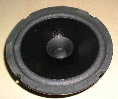
Here is a picture of the driver which has a coated paper cone, a foam surround and a whizzer cone to extend the upper frequency range.
|
| Site menu
Page menu
|
|
|
Skeleton (chassis perhaps), anyway the bit that will hold the driver in place and to which the baffle will be attached.
|
|
Again, in trying to make this design easy to replicate, the choice of materials is quite wide and even different sizes won't alter the sound as much as with a 'box' speaker. So even if you have never built a speaker before, this should be relatively easy to build and is quite forgiving of those not blessed with practical skills.
|
|
Materials
My choice of materials for the skeleton was 12mm chipboard but MDF, plywood or any other sheet material will work equally as well. You could use 18mm or 22mm thick sheets for greater strength but at greater cost. (You would also need to modify the sizes that I give for this design).
|
|
Apart from the chipboard, some one inch squared (25mm by 25mm) timber is used to strengthen joints and provide fixing points. I managed to complete my pair of speakers with just two sheets of chipboard, four feet by two (1200mm by 600mm) and about 24 feet (8 metres) of the inch by an inch (25mm x 25mm).
|
 |
For the panels you will need polystyrene sheet of the type sold in builders merchants. One length about 8 feet (2400mm) long by 2 feet (600mm) wide is required of the 50mm thick sheet for the front baffles. Two lengths of the same size but 25mm thick sheet are used for the side baffles.
|
|
Apart from the above materials you will need:
- some old hardboard of ply of a similar thickness
- a tube of building adhesive (the sort used instead of nails)
- a small tube of silicone sealant
- about 40 one and a quarter inch (30mm)No 6 screws
- about 20 two inch (50mm) No 10 screws
- 8 three quarter inch (20mm) No 6 screws
All the screws should be of the type that is suitable for driving into the chipboard.
- 8 M5 bolts about three inches (75mm) long with nuts and washers
- A short length of wooden dowel about the size of, and no bigger than a pencil
- A set of spikes for the base
|
|
Method
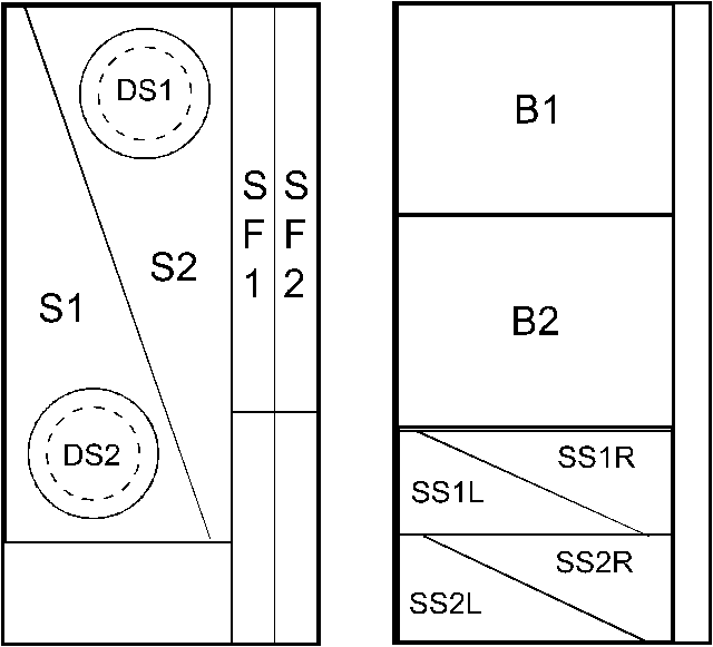
All the sheet materials for the two skeletons can be cut from two sheets of 12mm chipboard as shown in the diagram below.
|
|
|
|
S1 and S2 are the 'spines'. Cut from rectangles 40 inches (1010mm) by 18 inches (460mm). The diagonal cut runs between points two inches (50mm) in from each edge.
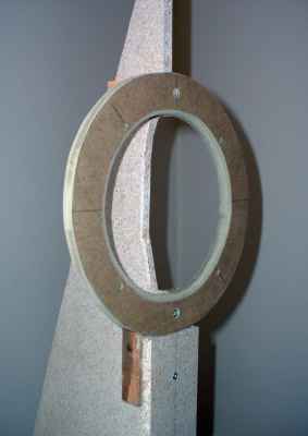
DS1 and DS2 and the driver supports. These are cut from the 'spines'. To establish the position of the driver support pieces, draw vertical and horizontal lines 7 in (180mm) from the front edge and base of the spine. These lines will later be useful for aligning the driver supports centrally on the spines. When cutting out the driver support, it is easier to cut the driver cutout (7.1 inches (180mm) diameter) first, then the actual circular support itself (11 inches (275mm) diameter).
SF1 and SF2 are the 'spine fronts'. (The line separating them isn't shown on the diagram). These are cut from the strip left over after cutting the spines. Each one will be about 3 inches (75mm) wide)
B1 and B2 are the bases - 21 inches (530mm) by 18 inches (460mm)
SS1L/R and SS2L/R are the 'spine supports (left and right sides).
|
|
Cut out the pieces as shown in the diagram. There will be some off cuts left over but don't throw them away yet! Run some coarse sandpaper over all the edges to remove any roughness.
|
|
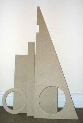
The skeleton parts cut from chipboard.
|
|
Take the driver support and using the crossed lines that you drew when marking its cenre, place a driver in the 'ring' so that the fixing holes are at 45 degrees to the crossed lines. Mark where the holes are on the support, remove the drive unit and then drill four holes the same diameter as the holes in the driver.
 - Countersink these holes on the front side of the support. It will help the bolts locate in the holes. - Countersink these holes on the front side of the support. It will help the bolts locate in the holes.
|
|
Assembly
Place the driver support at the top of the spine so that it is situated centrally. The lines you drew to locate the centre of the support will help. Mark where the inner edges of the support ring cross the spine. Now, using a jigsaw, cut a recess in the spine about one a half inches (40mm) deep. Then glue and screw the support ring in place. Add support to the ring with pieces cut from 1 inch (25mm) square timber that are glued in position.
|
|
Measure from the bottom of the support ring to the bottom of the spine, and cut a piece of SF1 or SF2 to the same length. Glue and screw that centrally to the front of the spine.
|
|
Take a base panel and draw a centre line from front to back. Draw a line either side of this so that the distance between them is the thickness of the panels that you are using. Turn the panel over and drill a hole in each corner to accept the T-nuts for the spikes feet if you are using them. Hammer in the T-nuts.
|
|
The next bit is easier if you have a large vice, or workbench with jaws. Line up the spine assembly on the base and glue and screw them together. The front of the spine assembly should be flush with the front of the base panel.
|
|
The lower part of the skelton.
|
|
Trim the width of the pieces SS1L and SS1R so that they fit between the spine and the outer edge of the base panel but allowing for a 1 inch (25MM) batten and 1 inch (25mm) side panel along the outer edge. Using screws and glue, attach the panels SS1L and SS1R to the spine at right angles so that they butt up to the spine front panel. These should ensure that the spine is rigidly supported at right angles to the base.
|
|
Cut suitable lengths of 1 inch (25mm) square timber to strengthen the joint between the spine and the base panel. Cut some more one inch (25mm) square battens to run from the front of the base to within two inches (50mm) of the back. Glue and screw these in position so they form rebates to accept the side panels.
|
|
The driver mount - front view.
|
|
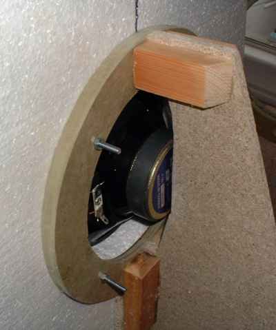
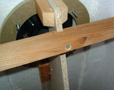
The driver mount shown from the rear. The sound should benefit from a wedge inserted between the driver magnet and the spine.
|
|
From the off cuts of chipboard, cut some pieces to go at the front of the spine supports to bring that surface parallel with the front edge of the spine and base panel. Glue or scew them in place.
|
|
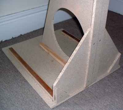
This completes the construction of one skeleton which should resemble the one shown in the picture below.
|
|
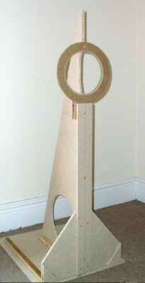
A completed skeleton.
|
| Site menu
Page menu
|
|
|
Think of the baffle as the 'skin' of this speaker. To make the 'skin', start by cutting the 50mm thick sheet of polystyrene in half so that each piece is about four feet (1200mm) long. Now cut each piece so that it is just over 18 inches 460mm) wide. Cutting the polystyrene is quite easy with a handsaw or jigsaw. Don't worry too much about the cut as it is quickly and easily cleaned up with a piece of sandpaper.
- If in doubt, cut slightly larger than you need and sand down afterwards.
|
|
I radiused the top corners of the front baffles as shown in the picture of the finished structure.
|
|
Cut two side panels from the 25mm thick polystyrene. Each piece should be 30 inches (770mm) high and 21 inches 535mm) wide. I also radiused one corner of each panel as shown in the picture of the finished baffles. Then cut a top panel 18 inches (460mm) by 12 inches (300mm).
|
|
On one side of a front panel draw a line up the centre. Use this line to place the panel centrally on the front of the skeleton. While holding it in place with one hand, use a felt tip pen to mark through the aperture of the driver support ring on to the polystyrene front panel. Carefully cut out this circle using a jigsaw. Try it for size with your drive unit. It will probably be just too small so carefully use sandpaper to enlarge the aperture until the driver fits snuggly.
|
|
Place the front panel back in position against the skeleton. Insert the driver so that it is flat on the front panel. The back of the driver should just fit into the recess cut in the top of the spine. Take a bolt, M5 by 75 mm (3 inches) and push it through one of the mounting holes in the driver support. Keeping it nice and square, force it through the polystyrene until it comes out through one of the holes in the driver. Withdraw it and push the bolt through from the front and loosely attach a nut. Do the same to the other three mounting bolts. Tighten the nuts so that the driver is pulled tightly against the polystyrene. Take a sharp knife or scalpel and score the polystyrene around the edge of the driver to a depth of about one quarter inch (6mm). Continue to tighten the nuts so that the driver is pulled into the polystyrene until it sits flush.
-When tightening the nuts, do a few turns on each nut at a time so as not to twist the driver frame.
|
|
Now time for some more cutting. Using a hole-saw, cut out 19 discs (for each speaker) from some scrap hardboard about 3mm thick. Cut 11 discs about two inches (50mm) diameter and 8 discs about one and a half inches (35mm) diameter. Finish these discs by countersinking the holes to accept No.10 screw heads.
|
|
Using two of the 2 inch (50mm) discs, screw the bottom of the polystyrene panel to the front of the skeleton. Use No 10, 2 1/2 inch (60mm) screws driven through a disc and score the polystyrene so that the discs are pulled in flush.
|
|
From the off cuts of 1 inch (25mm) thick polystyrene, cut pieces approximately 2 inches (50mm) wide and glue them to the back of the front panel using silicone sealant. The strips should be placed vertically to form rebates of a suitable size to accept the side panels, ie 25mm.
|
|
Cut two short lengths of 1 x 1 inch (25mm²) about 2 inches (50mm) long. Drill a hole near one end and screw them to the top rear ends of the 1 x 1 inch (25mm²) rails that form the rebate on the sides of the base panel so that the ends of both pieces are flush.
|
|
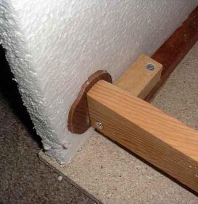
How the side baffle attaches to the base.
|
|
Cut four lengths of one inch (25mm) square timber, 16 inches (410mm) long. Drill a pilot hole to accept a No 10 screw centrally in each end of each length, then countersink these holes. (This makes it easier to locate the screws into holes).
|
|
Offer up the side panels so that they sit in the rebates on the front panel and base panel. Use some sticky tape to temporarily hold them in place. Mark the middle of one of the lengths of 16 inch (410mm) timber and place it across the 'spine' of the skeleton quite near to the top. Drill a hole so that you can secure it to the spine with a suitable screw. Now using a large disc on the inside, and a smaller disc on the outside push a No 10 2 1/2 inch (60mm) screw through the polystyrene side panel so that it is aligned with the pilot hole in the 1 x 1 inch (25mm²) timber. Screw in the screw so that the discs are drawn tightly against the polystyrene. Do the same on the other side. Then, using a sharp knife, score around the outer disk and tighten the screw further so that the outer disc is pulled in flush with the surface of the polystyrene. Repeat on the other side
|
|
Position of the 'top rail'.
|
|
Now attach another one of the lengths of 16 inch (410mm) timber at the bottom rear so that this 1 x 1 inch (25mm²) lines up with the two short lengths that you attached earlier. Drill appropriate holes and screw the timber to the short lengths using suitable screws.
|
|
Repeat the process again for the remaining two cross pieces, one in the centre of each panel and the other at the top rear. Neither position is absolutely critical!
|
|
Now place the top panel on top of the side panels butted up to the front panel. Make four wooden pins from the dowel about 2 inches (50mm) long. Use a pencil sharpener to make a point on one end and push them through the top panel into the side panels. Be careful to push them through squarely so that they don't break out of the side panels. Push them just below the surface of the polystyrene using a screwdriver or other suitable tool. You could use silicon sealant to stick the top panels down or pieces of strong sticky tape.
|
|
Finally, cut the two remaining 2 inch (50mm) disks in half, drill and countsersink two small holes in each half and using 3/4 inch (20mm) screws, screw each half to the base sides near the front so that the bottom of the side panel is held in place.
|
|
Now, using sandpaper, carefully sand all the edges flush and smooth. I put a nice curve on the edges.
- cut a section from some plastic pipe to make a curved former that holds a piece of sandpaper.
|
|
Sanding tool for curves made from section of plastic pipe.
|
|
The wonderful thing about the polystyrene is that you can shape it very quickly but be careful not to make any big mistakes. If you find that you have score marks on the flat surfaces after sanding the curves, just use sandpaper and a flat sanding block to remove them.
|
|
Warning, cutting and sanding the polystyrene makes quite a mess. The polystyrene 'dust' is easily hoovered up afterwards but if you share your home with a SOH, don't tell them that I gave you the idea of working with this stuff!
| SOH - Significant Other Half, eg girlfriend, wife or mistriss!
|
|
And that's completes the construction of the open baffle structure.
|
|
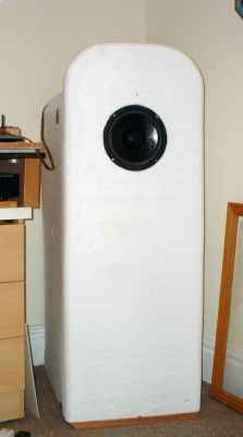
A completed structure before papering.
|
|
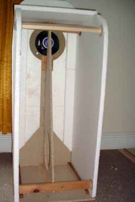
A completed structure - rear view (but before adding centre 'rail').
|
| Site menu
Page menu
|
|
|
Unscrew the side panel structure from the skeleton, carefully remove it and then paper it with an embossed wallpaper, inside and out to increase it's strength and decrease the sound transparancy. I prefer to use an embossed paper for this job because
- It is stronger than a flat paper
- The uneven surface defracts the sound waves
but you could also use a flat paper if you prefer.
|
|
After papering, the side baffles assembly can also be painted.
|
|
As regards the front baffle, I have not yet decided how to finish that yet but will probably use paper mache which will be sanded down and painted.
|
| Site menu
Page menu
|
|
|
The speaker could be used as it is but that is not the optimum arrangement. With a comparatively small baffle like this (yes they go a lot bigger), it is a good idea to try and attenuate the rear sound wave. Attenuating the rear wave will be the tuneable aspect of this spaker project, and no doubt, an on-going work!
|
|
To begin with, I am going to use some net curtain material suspended from the top two 'rails' of the side baffle assembly. The material will be draped around the bottom 'rail' forming a V shape behind the drive unit that can be filled with various types of stuffing. I will start off with polystyrene packing chips (what else) and also plan to try holofill stuffing (from pillows). Fibreglass (yuk) and teased sheeps wool are other options but please don't take the DIY approach to the sheep's wool unless you are good friends with the farmer!
|
|
Alternatives for the holding material are anything that is acoustically transparent. Materials suitable for speaker grills will be fine. The material can be pinned to the 'rails' or temporarily held in place with spring clips. There won't be (or shouldn't be) much weight inside so there is no need to go over the top with your fixing method. If you make the fixing to the top rear 'rail' easily removeable, you will be able to empty any filling if and when you change to another type.
|
| Site menu
Page menu
|
|
|
Well, I must start this section with the statement that these are my first impressions with the drivers not 'run in' and with no real attention to the rear wave attenuation, other than a piece of foam and a thin curtain thrown over the rear aperture.
|
|
But let's get down to business as, judging by the response to this project on the 'Full-range Driver Forum', there are more than a few people who would like to know what this speaker sounds like.
|
|
I'd better begin by describing the system used with the speakers. It consists of a Cambridge Audio CD5 CD player with some slight modifications. A stepped attenuator sits between this and a pair of Gainclone monoblocks that drive the speakers. The testing room (not my main listening room) is around 11 feet (3.3 metres) square. The only real option is to have the speakers in the corners such that the drivers are about two feet (600mm) from the rear wall and slightly toed in.
| Toed in - pointing inwards toward the listening position. This can help with the stereo image. For best results, the exact angle of the speakers is ascertained by trial and error.
|
|
First into the CD drawer was Norah Jones. Vocals were a little dry sounding but otherwise clear and up front. With the speakers doing their 'invisible' act, it did seem that Norah was right there in the room! I judged the level of the double bass to be a little down compared with the Mordaunt Short Pageant (ported boxes) speakers (MSP's) that I have been using to test the Gainclones until now. But what was lost in amount was made up for by quality with a more realistic rendition. At one stage I noticed the resonant sound coming from inside the piano, something that I hadn't done before! The only other note I made from this album was that sometimes the symbols seemed a litte 'rolled off'.
|
|
Moving on the Massive Attack album, No Protection, bass levels were clearly down on the MSP's but in actual fact, I prefered it like that and thought the track, Cool Monsoon actually sounded better for it. Was this track originally mixed for the ghetto-blaster brigade and the bass levels boosted accordingly? The sound was also not so 'clinical' as with the MSP's although each little sound was portrayed clearly and separate from the others. As you would expect with no crossovers, the transients were very good.
|
|
Some opera featuring Placido Domingo (Maltinata) was most enjoyable and although I am perhaps used a more 'scale' (with the 12 inch Goodmans 201's), the orchestra was well positioned (correctly) and the dynamics were good. I couldn't be certain, but Domingo sounded just a bit further away from me than he does with the MSP's.
|
|
Sticking with classical but moving up tempo, Bond (Strange Paradise) surprised me in the that the bass beat seemed as loud as with the MSP's. Timing was great and I could clearly hear the catgut of the violin bow 'rubbing' across the strings.
|
|
At this stage I was thinking of suggesting this as a good speaker for jazz and acoutic music but I was soon to change my mind on this when I played some Jackson Browne. Never Stop (from the album The Naked Ride Home) surprised me to say the least with the level of bass. Maybe not quite as deep as with the MSP's but plenty of it and really stomping along in perfect time to the rest of the music. In fact, I enjoyed a couple of tracks from this album more than I have with the MSp's, or even in my main system! I was slightly more aware of the speakers with this album but mainly due to the mix where symbols are sometimes mixed on the left or right, rather than centre stage. I did make a note of the fine metallic sound of the symbols. And at times, you could clearly hear the sound of the sticks hitting the drums, rather than just the drum beat itself. I also found that I could play this album much louder without causing problems with the bass. This confirms that open-baffle speakers do work very well with the room and remove many of the problems that other types of speaker have with reproducing bass in 'difficult' room sizes. On one track (The night Inside Me) there was just a glorious wall of sound when everybody joined in the chorus, rather than being compressed into the middle of the soundstage. Yes, you can tell that I enjoyed that bit!
|
|
Eva Cassidy was next up for audition. Fields of Gold (from the Songbird album) revealed a slight roughness that I believe is attribuatable to the newness of the drivers. I would say that her voice was not as warm as I have heard it with my other equipment but that may be a more accurate representation! Once again, it was as though the singer was 'in the room'.
|
|
One of my standard tests for clarity is to use track 2 from the Pink Floyd, Dark Side Of The Moon CD. Listen for the lady announcing the flight to.... and see if you can hear the three destinations. I could easily do that with the new speakers and also listened until the clocks started chiming at the start of track 3 but did't think that they were as clear as with the MSp's and my main system.
|
|
Lastly, for this session, I put on Roger Walter's Amused To Death (track 6) and listened to see how far out from the speakers the raindrop came. On the next track, a coach and horses can be heard riding across the room and again, should come very close to, or even behind the listening position, depending a lot on the listening room dimensions. On both these tracks, the result was about the same as with the MSP's but nowhere near as good as with my main system. Until I test this system in the main listening room, I can't really make a fair comparison.
|
|
Summing up, I am more than a little pleased that a speaker of this cost, that is comparitively easy to construct, should produce such good results with the drivers not yet run in. At no time did I feel that one frequency was a bit too much for me; nothing 'shouted' at me and I never felt as though I wanted a break from listening. In fact I enjoyed myself so much, I was late to go round a do and job for my mother!
|
|
Bass-wise, I didn't feel it was missing enough to really matter but I do appreciate that I was listening in quite a small room and the same speakers used in a larger room may not fair so well.
|
|
I am impatient now to see how well the drive units break in and what happens to the sound quality as they do. I believe that there is a modification that can be made to the whizzer cone that may also make improvements.
|
|
Words come into languages and after a while they tend to loose their original meaning, or at least the meaning is less specific. Hi-fi is an abbreviation of High Fidelity, the original idea that it applied to equipment that faithfully reproduced sound such that it was true to the original performance. Taking that original definition, I think that it is fair to say my new speakers are 'hi-fi'; certainly much more so than many of the commercuial offerings that I have auditioned in hi-fi shops. It may not have a super-flat response (I'll try and measure it some time) but it does do a creditable job of trying to reproduce music as it sounds in real life. The results are certainly good enough for me to try and develop this concept further, and to recommend that better quality drivers be tried as well.
|
|
I'm not touting this as the ultimate speaker, or anywhere near it. But for the cost and effort, it does do some of the things that top speakers do well and it's shortcomings are easy to live with. Paired with the Gainclones, it offers a real taste of high-end sound that you could spend many years trying to emulate buying commercial hi-fi!
|
|
I know there is plenty of work and testing still to do and I will update this page as and when I have something new to report. And now, if you'll excuse me, I'm going back to listen some more!
|
|
UPDATE 31th May 2003
I have now removed the sponge foam material and curtains and replaced them with the net curtain material filled with polystyrene chips. I used net curtain material purchased locally. The piece bought was 48 inches (1200mm) wide and seven feet (2 metres) long and cost me £1.20!
|
|
I cut the material in half down the length and then draped a piece over the top 'rail' of the side baffle assembly and pinned it in position using drawing pins(thumbtacks). The material was then pulled tight and pinned to the bottom 'rail' in the same manner before being taken up to the top rail and pinned. I used masking tape to stick the extra material to the baffle sides and then poured in enough polystyrene chips to fill the V shape to the top 'rail'. Then I piled more chips on the top of the speaker and holding up the extra material with one hand, I swept the chips into the net so that they came almost to the top of the baffles. I then neatly folded the material and pinned it to the tip of the side-baffle assembly. (Not an ideal permanent solution but it works).
|
|
The chips I got for free from a couple of local shops. They are widely used and you shouldn't have much trouble in finding a shop-keeper who is glad to have you take them off their hands.
|
|
With the polystyrene chips now effectively blocking the rear aperture, some may now argue that what I have is not an open baffle speaker but an aperiodic box! I can't argue against that as the thought crossed my mind as I was putting in the polystyrene chips. But let's face it, this is one extremely leaky box and many open baffle designs have some sort of absorbant material behind the drivers. And I'm not particularly worried what category the design falls into, but how it sounds.
|
|
I don't know if the bass levels will come up high enough with an open baffle speaker of this size to satisfy everybody, particularly in a larger room. I would say that some sort of subwoofer would be required and of course that would add substantially to the cost of the system. A dipole sub would seem to be the best choice although I have been told that they just don't go low enough. As I have no experience of them I cannot confirm or deny that but obviously further research would be required prior to choosing a subwoofer. But please don't let me undersell these speakers. There is plenty of bass there and certainly no less than with many small 'box' designs. And to repeat myself, the quality of that bass is far superior to most 'box' designs. A lot will depend on the musical tastes of the listener, the partnering equipment and the listening room.
|
|
During this last week, I have been listening to the 'new' speaker system in one room with the Gainclones, and then to my 'main' system in another room. The two sound quite different, the 'main' system sounding very smooth and 'hi-fi', the other a bit rougher but more 'live'. Hi-fi is nothing if it is not about compromise and I think that my experience this week has reminded me of that fact!
|
| Site menu
Page menu
|
|
|