|
Decibel Dungeon
|
|
|
|
Introduction
Well. I had no intention of building a Gainclone, I had heard of them and even read a very good review of one of the commercial designs produced by Final Analysis. Then one day I was surfing around looking for information on building a valve pre amp when somehow I found myself on a DIY audio forum. Perhaps tired of looking at valve information, I clicked on a link and found myself on a thread about building chip amps that the builders had come to call Gainclones.
|
|
 Gainclones, are so called because the original inspiration is a commercial product called the Gaincard amplifier, produced by 47Labs. This was the other commercial amplifier using a chip amp that had received rave reviews from the hi-fi press, and not a little controversy due to its selling price in relation to its material cost. I won't get into that argument. My view is that in a market place of many products, if a customer will pay a price for something, that is up to them. Gainclones, are so called because the original inspiration is a commercial product called the Gaincard amplifier, produced by 47Labs. This was the other commercial amplifier using a chip amp that had received rave reviews from the hi-fi press, and not a little controversy due to its selling price in relation to its material cost. I won't get into that argument. My view is that in a market place of many products, if a customer will pay a price for something, that is up to them.
|
|
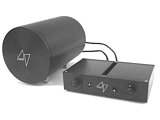
 The battery driven Final Analysis Music-6 chip power amplifier. With battery meter and damping control. The battery driven Final Analysis Music-6 chip power amplifier. With battery meter and damping control.
|
|
Anyway, back to the story. I found the thread fascinating and when I saw pictures of the efforts of one Gainclone builder, Peter Daniel of Canada, I was hooked enough to want to build one for myself. I think that my main motivation was to actually hear one of these amps for myself. Usually when you read reports on hi-fi equipment, you will have to rely on the honesty/opinion of the writer as there will be little chance to hear that item for yourself. In the case of the Gainclone, the cost of building one is not prohibitive, even to those of us working on a fairly tight budget.
|
|
In my case, I already had the two most expensive parts of a stereo Gainclone, the mains transformers, these being the original items from my modified Arcam A60's that had been replaced with more powerful ones. Out came the spreadsheet, and using one of the simpler designs, I worked out that I could build my stereo pair of Gainclones for under 50UKP. As I was already spending money on my valve pre amp project, I resolved not to spend more on the Gainclones without getting that money in first by selling off some stuff on Ebay. A couple of weeks later I had raised 60UKP and got down to the serious business of researching the project further and drawing up a final design.
|
|
IMPORTANT - if you are new to building hi-fi, please read the following.
or click HERE to skip this advice for beginners.
|
|
The Gainclone is almost unique in DIY hi-fi in that it is such a simple design with so few parts. For that reason it has attracted many would-be builders who have perhaps never built any electronic equipment. Reading the chip amp forums, there are stories of failed attempts and (so far) minor disasters, due to inexperience. While I do not believe that it is the responsibility of sites like Decibel Dungeon to 'hold peoples hands', in this case I feel that some good basic advice wouldn't go amiss!
|
|
So here is some extra advice that I hope will help the less experienced builders get their Gainclone working (safely) first time.
|
|
When building your power supply:
- Use a fuse on the primary side of the transformer, ie between the on/off switch and the transformer. A 1.6AT fuse should be suitable for most Gainclones.
- Not essential but highly recommended are fuses on each of the rails, ie between the rectifier bridge and the amp. These should be 3.15A fast blow types. Use these to get going and when you are confident that your amp is working OK, then you can remove them if you want to.
- Make sure that you have the correct transformer. There is no one specification but ideally the secondary voltages should be between plus and minus (+/-) 18 volts and +/-24 volts. The VA rating of the transformer should be no less than 120VA (or 80VA if you are building a PSU for each channel).
- If your transformer has twin primary leads and/or twin secondaries, make sure that you know how to wire it up correctly. The supplier should be able to tell you which leads are which.
- For the rectifier bridge, stick to rectifier diodes of the types you see recommended by other builders (mine are on this page). Don't try and be clever and use something that you have 'in a drawer' unless you are sure that it is correctly rated for the job.
- I provide a diagram of how to wire up a rectifier bridge. Follow it exactly and if you have any questions ask before you connect power to it.
- Get into the habit of using a standard colour system for your wiring. I use red for positive voltage (+), black for negative voltage (-v), blue for zero volts (0v) and green or yellow for earth.
- Don't use any capacitors in the PSU to begin with. This is one (two actually) less thing to get wrong.
- When you have built the PSU, check and recheck the wiring of each and every component, go and have a break, and then check them all again. If you are happy that all is correct, plug the PSU into the mains and then measure the voltages on the output connector. You should have a plus voltage and a minus voltage that are the same value (give or take a small amount). If you don't have the correct voltages, get some help and don't connect the PSU to the amplifier circuit.
- Make sure that all conductive parts that carry mains voltage are well insulated (even on prototypes PSU's built out of cases).
- If using a metal case, make sure that no wires are making contact with it and causing a short circuit.
When building the amplifier:
- OK, so you are new to this game and you are not expected to understand a circuit diagram but do study the design that you are going to build and at least understand where each component goes and how it connects to the others.
- As with the PSU, get into the habit of using a standard colour system for your wiring. I use red for positive voltage (+), black for negative voltage (-v), blue for zero volts (0v) and green or yellow for earth.
- Don't substitute parts in a design unless you are completely sure that you know it is safe to do so. Again, don't just use a part because you already have it. As a rule take your rails voltage and multiply it by 1.25. That is the minimum voltage that your capacitors should be rated at.
- Make sure that the chip is insulated from the heat sink. Use an insulator like the one I used. Make sure that there are no sharp burrs on the heat sink that can pierce the insulator and make contact with the chip.
- Use an adequate sized heat sink.
- Make sure that you connect any polarised capacitors the right way round. Check with the circuit diagram, then recheck and again after you have soldered the capacitor in position. Inserting capacitors the wrong way round is one of the most common mistakes made by newbies!
- Try and get a ready-made PCB. If not and you choose to go with point-to point' wiring be very careful. First, take some time to plan out where each item will be located. Do a dry run and lookout for any potential problems. Try and keep wires and leadouts as far away from each other as possible. Where it is not possible, sleeve the wires/leadouts with sleeving taken from scrap wire.
- Study how to wire the circuit properly, especially the grounding.
- If using 'point-to-point' wiring, glue components in position to take the strain off the soldered connections. Hot melt glue is ideal for this job but solder first, then glue.
- Keep all wiring as short as possible.
- Keep the decoupling capacitors as close as possible to the pins of the chip (+v and -v).
- It might sound obvious, but make sure you connect the right items to the right pins of the chip. Understand the difference between the positive and negative voltage connections and the negative and positive signal connections.
In general:
- Make a drawing of the circuit showing where each part will go.
- If using separate housings for the PSU and amp, make sure that your umbilical lead joining the two is well constructed and that the wires are firmly connected to the plugs/sockets. Don't use the same type of plugs to connect the mains to the PSU and the DC supply to the amplifier. Make sure any plugs or sockets are correctly rated for the job.
- You will find it easier to build the PSU and amplifier sections onto a piece of board or timber at first and leave everything open so that you can see what is going on. If RFI is a problem, you can deal with it by putting the amp into a shielded case later.
- When powering up, wear some eye protection and stand back (although behind the sofa isn't really necessary).
- BEFORE you connect the amplifier to your speakers, measure the DC offset voltage. Insert two speaker plugs (bare, ie minus the plastic bits) in the speaker terminals of the amplifier. Solder one end of a 10 ohm resistor (any type will do) to each of the plugs. With the amplifier powered on, measure the DC voltage across the terminals (either side of the resistor). Start with your meter on the 200v (DC) range. It should read zero, if so go to the next range down and so on until you get to the lowest range. Depending on the actual circuit design, you should have no more than 30 milivolts. If you have ask for some help and don't connect your speakers. If the DC offset is OK, switch off the amp before connecting the speakers.
(Also, see the Gainclone FAQ section).
There may be a few things that I have forgotten and if you can think of anything that I should include in this section please email me. You could save somebody disappointment!
|
|
Footnote
It took me two and a half hours to write this section for beginners. It will only be worthwhile if you take note of what I have written! Why not cut and paste this section, print it out and keep it near you as you build your Gainclone?
|
| Site menu
Page menu
|
|
|
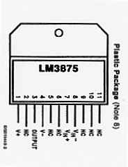
When it comes to hi-fi (or anything else) I favour the most simple approach. The Peter Daniel amp that I had seen, used a very simple circuit which is in turn a modified version of a design proposed by Thorsten Loetch. Thorsten had studied the chip amp designs and suggested using an inverted design that used fewer components than the non-inverted circuits and which, in theory at least, should sound better. It used the LM3875 chip which seems to feature in most of the designs that you will see when surfing the chip amp sites although other chips are popular too. You can expect to hear a lot of debate over which is the best chip for an audio amplifier as this part of DIY hi-fi grows more popular, as it surely will!
|
|
Peter Daniel had stripped Thorsten's design even further as the latter had wanted to ensure that his design would work safely in a variety of systems (Thorsten has now refined his circuit for the inverted LM3875 that improves its stability in virtually any system). I decided after looking at several designs to use the PD circuit and turned my attention to the power supply.
|
|
Thorsten recommended a separate power supply for each channel with a separate rectifier bridge for each rail. To achieve that, a transformer with twin secondary windings is required and my transformers didn't have them. So, I settled on one power supply for each channel with a single rectifier bridge supplying both rails.
|
Secondary windings - a transformer consists of wire wound around a former. The coils of wire that are formed pass electricity from one to another by the process known as Mutual Inductance. One coil is connected to the mains supply and is known as the primary. The other coil is known as the secondary. The primary voltage is that of your mains supply and secondary voltage is determined by the ratio of turns in each coil. Transformers may have more than one primary or secondary coil. Two secondary coils are useful for more complex PSU designs or just for providing different secondary voltages, eg for CD players that require voltages for opamps, drive motor, display etc. More.
|
|
The rectifier bridge can be a ready-made item or built from individual diodes. You will hear arguments for both types. Dejan Veselinovic puts the case for using a read built bridge on the grounds that with the diodes built on the same silicon substrate, they are much more closely matched than is possible using individual diodes. I was going to start with a ready-built bridge but then I got drawn into another forum thread on diodes and after much deliberation, decided to go with individual diodes, choosing the MUR860's (931-020) that Peter Daniel had been so pleased with. I also decided to place snubber capacitors across each diode to reduce the amount of noise produced as they turn on and off. As there are (unusually) no capacitors specified for the Gainclone power supply, the only other items to put on my ordering list were the mains switch, fuse and fuse holder and some wire and connectors.
|
|
As ever, there are options for adding items like switches, fuses and connectors so I'll just state what I have used here for those that want to copy my design. (All part numbers quoted are for items from Farnell unless otherwise stated) I used a miniature DPST mains switch (157-790 ), a snap-in panel-mount fuse holder (147-910 ) and 50mm 1.6AT (anti surge) fuse (533-891 ). I use a captive mains lead that enters the case through a cable gland (Maplin code UP89)that adjusts to hold it securely in place.
|
|
This all involves cutting three holes for the switch, fuse holder and cable gland in the back panel of the case. For this reason, some people prefer to use one unit for all three functions, ie it has a mains inlet socket, a fuse holder and an on/off switch in one unit so you only need to cut one hole. Which you use is up to you but a suitable 'all-in-one' solution is part number 964-463 from Farnell.
|
|
For connecting the power to the amplifier, I use a captive lead, exiting the PSU case through another cable gland and connected by a Speakon 4 pole connector (152-305) to a matching socket (152-306) mounted in the amplifier case.
|
|
Finally, the casing that I used and which is ample to hold the transformer and rectifier bridge with a bit to spare, is from , part number XB71.
|
|
Click HERE for a spreadsheet listing all the items needed to build the simplified Gainclone described on this page. I have tried to cover virtually everything that you will need but some items defy a clear specification or costing so please take note of the following:
- The items shown are to make one channel so double up everything for a stereo pair.
- Cost of wire is not shown. If separate cases for PSU and amp are used, you will need to construct an umbilical cable to join them. For that, solid core 0.6mm diameter wire sounds very good but is liable to break easily if the umbilical gets moved around. This could lead to 'cooking' a speaker so be warned. An alternative is 16/0.2mm stranded wire.
- Some material to construct your rectifier bridge on (unless using a ready-made bridge). You could use strip board or veroboard.
- A mains cable and plug. This will depend on how far away the mains socket is and the type of plug used in your country. With so many electrical items being thrown away, you really should be able to find mains leads for nothing!
- A screw to attach the chip to the heat sink.
- Hot melt glue is very useful to glue down components that are hard-wired to the chip pins. If you don't secure them, and they can move about, they will put undue stress on the pins which could break and/or cause a disastrous short short!
- Sleeving. Again, to minimise the chance of a short circuit, use sleeving over bare wires and leadouts when ever possible. You can get the small amount needed by stripping it off scrap cable or wire.
- Some wood or MDF to make thick bases for the aluminum cases. This really does make a difference to the sound.
If you use the ready-made aluminium cases, the tools that you will need to complete a Gainclone are:
For the case work and umbilical:
- Electric drill with suitable drill bits.
- Hole punch and/or metal files depending on shape and size of switches etc.
- Philips and small flat-bladed screwdrivers.
- A small hacksaw to cut the rectifier bridge board.
- Wire cutter/strippers.
For the amplifier:
- A soldering iron and solder (and possibly a solder sucker).
- A drill and tap to make a threaded hole on the heat sink to screw down the chip.
- Wire cutter/strippers.
- Small needle nosed pliers to hold small components while soldering.
- A multimeter.
- A magnifying glass is very useful but not essential.
- Philips and small flat-bladed screwdrivers.
- A hacksaw.
|
| Site menu
Page menu
|
|
|
As I write this, my PSU's are working but still not built into a case. After several aborted attempts at building some cases that did not look as good as they did on paper, I ordered some aluminium boxes from Maplin and am still waiting for them to be delivered.
|
|
In order to get my amps 'up-and-running', I built the PSU's onto slabs of timber about 250mm by 150mm. The transformers were bolted to the wood and then two 'side panels' were screwed to each side of the wood. One panel houses the on/off switch and the fuse-holder, the other supports the rectifier board. A few terminal blocks link all the wiring together.
|
|
 This is how the rectifier board looks from the top. One pair of rectifier diodes (MUR860's) are face up and the other pair face down. The snubbing caps (not shown) are soldered to the pins of the diodes underneath the board. The connections between the pins of the diodes are made on the underside of the board. The supply leads from the transformer are attached through holes in the board as shown. The DC leads are attached under the board and come through holes to enter the terminal block. The zero volt wire from the transformer goes straight into the terminal block where it is also attached to a second terminal. This enables any smoothing caps to be connected to the terminal block (as can be seen in the picture below).
|
|
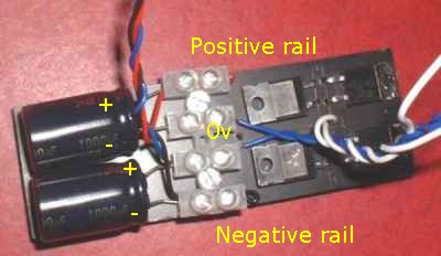 I used some fibreglass board for the rectifier bridge. Please note, the two 1000ufd caps were used for the picture only. In practice, I have found that 120 ufd's work well.
|
| Site menu
Page menu
|
|
|
 I'll talk about the casing later in this article, but for now I'll just say that I wanted to build the complete amp circuit onto the circular back plate of the amplifier casing. This circle is 100mm in diameter and provides just enough room to comfortably fit all the components on, including the by-pass capacitors. There is also enough room to allow for substituting different input capacitors. I'll talk about the casing later in this article, but for now I'll just say that I wanted to build the complete amp circuit onto the circular back plate of the amplifier casing. This circle is 100mm in diameter and provides just enough room to comfortably fit all the components on, including the by-pass capacitors. There is also enough room to allow for substituting different input capacitors.
|
|
 -I'll start with a tip. Try and get a chip (they come in different versions) that has stepped pins. This makes it a lot easier to solder the components and wires to it. -I'll start with a tip. Try and get a chip (they come in different versions) that has stepped pins. This makes it a lot easier to solder the components and wires to it.
|
|
The minimized Gainclone circuit that I used. Click on picture for large version
Click HERE for an alternative circuit (courtesy of Kim Schultz)
|
Please note. I used a 47 uF Black Gate capacitor on the input because I had some handy. I would normally use (and therefore recommend) a 2.2 - 4.7 uF film capacitor (eg polypropylene type) for this part of the circuit!
Update 2012 - that BG NXQ cap is hard to beat although very difficult to obtain now. But try a 47 uF Panasonic ECA and compare it to a film cap - you may like it better! Another option is a couple of non-polarized caps in series and soldered 'back-to-back'.
|
|
With most of the amplifier circuit included on the chip, there are remarkably few external components when compared to conventional discrete amplifiers! This is made clear in the picture below.
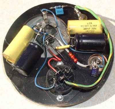
The amp built onto the back plate/heat sink.
|
|
I started by removing the pins of the LM3875 chip that are not connected (marked NC). The feedback resistor (or in my case two as I used two in parallel to double the power rating) was then soldered between pins 3 and 8. Then I attached the chip to the heat sink, using an insulating pad and plastic bush to insulate it from the connecting screw.
|
Double the power rating - this is said to increase the thermal stability and lower the noise level. An added advantage of using two resistors is the ability to achieve resistance values not attainable with a single resistor.
|
|
Next, I joined the decoupling capacitors to the bypass capacitors and soldered their leads together. Before doing this I had laid them on the back plate in the correct position to make sure that they did not overlap the back plate. The leads of the decoupling capacitors (that connect to the chip pins) are then carefully cut to length. When the capacitors are soldered to the chip, they are then stuck to the baseplate with a small dab of hot-melt glue. Do make sure that the capacitors are securely held to the back plate as the tiny pins of the chip are not at all strong and if a capacitor moves it may break a pin or worse still, cause one pin to touch another and cause a short-circuit!
|
|
I now turned my attention to the input section. As I was not including a pot in my amps, a 56K metal film resistor was soldered between the input of the phono socket and its ground tab (which I selected as the signal star point). The input capacitor was then soldered to the same socket input. Next, I cut the lead outs of the 10K input resistor to fit between pin 8 on the chip and the input capacitor, sleeved the lead outs and then soldered it first to the chip and then to the input capacitor.
|
|
The leads from the input connector were then soldered in position. The two power rails go to the appropriate pins on the chip (positive to pin 1 and negative to pin 4). The zero volt connection goes to the power star ground and the earth wire to the terminal bolted to the heat sink.
|
|
The power star ground is created from small solder tags that are then bolted together with a single nut and bolt.
|
|
Another wire runs from the star to pin 7 on the chip although this could be replaced with a 1K resistor which should reduce the DC offset voltage on the speaker terminals. I have yet to try this as I only get 28mV using the wire. I have also read that pin 7 should be connected to the signal ground star rather than the power ground star. I have yet to make this alteration but there seems to be no detrimental effect with the existing arrangement.
|
|
A connection is made from the star to the earth wire where it is connected to the heat sink. This connection is made through a 100R resistor with a 22nf capacitor in parallel.
|
|
Finally, the star is connected to the signal star (on the phono input terminal).
|
|
Wherever, wires came close to one another, I used sleeving removed from scraps of wire. This is vitally important when using hard-wiring in such a confined space. Even if two wires don't physically touch, a spark can still jump form one to the other.
|
|
And that's really all there is to building a Gainclone amplifier. It almost takes longer to write about it than do it but just because it is relatively simple, don't get complacent and make a silly mistake!
|
| Site menu
Page menu
|
|
|
There is usually two ways of accomplishing any DIY project; the easy way using readily available materials or ready-built components, and the hard way, doing your own thing and starting with raw materials and a pen and paper.
|
|
After two failed attempts to build the PSU housing using the hard way, I called it a day and ordered two ready-made aluminium cases. But this made me all the more resolved to 'do my own thing' for the amplifiers. I had decided from the outset to build two mono bloc amps that would give me the greatest versatility. And as these would not have a pot or input selector switch, they could be physically quite small. The compactness of the Gainclone circuit that enables it to be built onto a heat sink or back plate also means that the rest of the case need not conform to the rectangular 'norm'.
|
|
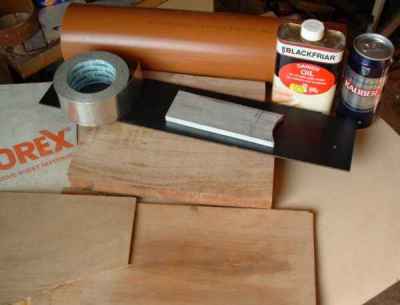
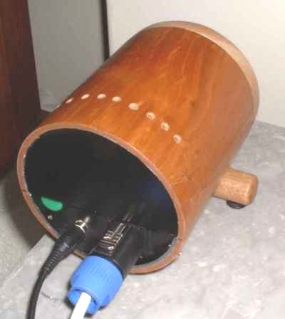
The raw materials for my Gainclone cases
I must admit that most of my designs are dictated by what materials I have in the house, or can obtain at little or no cost. Looking around the house, I saw the 110mm diameter plastic pipe, normally used as soil pipe by the building industry. I realized that this would provide a sturdy housing for the amps that would only require the addition of a front plate and back plate to create an enclosure. Of course, brown plastic isn't the prettiest sight in a hi-fi system but I also had some scraps of cherry wood veneer, left over from a previous loudspeaker project. I also had some fibreglass sheet material that would do for the back plate but what about the front plate. Fortunately, a visit to a friend who is a furniture restorer, and a spot of begging, saw me return home with a thick piece of attractive mahogany.
|
|
Cutting the pipe with a mitre saw was easy and I used a piece of scrap tube to mark out the faceplate's on the mahogany. I used a bandsaw to cut out the rough circles and then marked the inside diameter of the pipe on the circles and carefully cut away a 10mm rebate so that the front plates fitted snuggly in the pipe. I then used a drum sander to smooth the front plates so that they were the same size as the tubes with a piece of veneer attached. Holes were then drilled for the speaker terminals. These holes were stepped, so that an MDF plug could be inserted from the rear. This plug would provide the socket for a banana plug. The smaller hole in the front was then rounded using a router before the whole front plate was finished with fine sandpaper. This whole operation was a labour of love and would be a hundred times easier with a lathe!
|
|
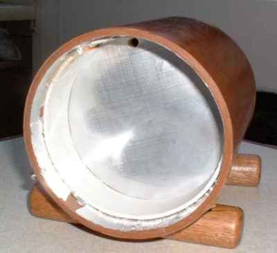
The internal compartment for the amp. Please note, that to improve cooling, I have since removed the 'partition'.
I wanted to create a compartment in the pipes for the amp. After thinking about this for a while I used a strip of flexible plastic (found in a skip some years ago) to make an internal collar. A circular disc of ply, the same size as the internal dimension of the pipe was cut and covered with a cut up beer can on one side and with self-adhesive aluminium tape on the other. A hole was cut for the (internal) speaker wires and the disc was then glued to the collar with hot-melt glue. Before inserting the collar I had stuck the aluminum tape to the inside of the tube and that makes contact with the disk and the metal heat sink providing a good RFI shield.
|
|
The back plate was made from a piece of black fibreglass sheet that has a smooth plastic coating on one side. I cut out a circle to fit inside the pipe and then cut a semi-circle of 10mm thick aluminium that was to be the heat sink. I cut holes in the fibreglass where the chip would be attached, and for the phono and power sockets. The back plate fits into a recess made by the collar inside the pipe (see above picture) and is held in place by two screws that hold another 'collar'.
|
|
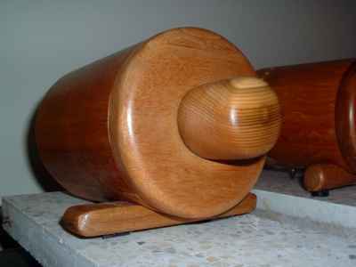
Veneering the pipe was straightforward. A hole was drilled in the bottom of the case at the rear end to accept a metal spike. I happened to have some 25mm mahogany dowel lying around and decided to use that to make the front support section. It was just a question of carefully shaping the dowel so that the veneered pipe rested in a curved cutout and then gently shaping the ends. Rubber tap washers glued to each end provide the non-slip feet. Five coats of Danish oil were then applied to the veneered pipe, front-plates and front supports.
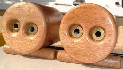
A pair of Gainclone cases (I wonder what they are thinking!)
|
|
While the finish was being applied, I built the speaker terminals. Circular pieces of MDF were cut about 40mm in diameter. A 3mm diameter hole was drilled through the centre of each 'plug' and using a hacksaw, grooves were cut on one face and one side. Four suitable lengths (two red and two black) of 0.6mm wire were cut and about 50mm of insulation removed from one end. The wires were then threaded through the holes, run along the grooves and then secured with a dab of hot-melt glue. A plastic counter (from a children's game) of the appropriate colour was then glued over the hole on the 'front' of each plug. When the plugs are inserted into the holes on the back of the front plate (still with me?) the plastic counters are visible through the smaller holes on the front of the front plate. The two plugs in each front plate are secured in position with a piece of the fibreglass sheet and a couple of screws so that they can be removed in the unlikely event that the wires break.
|
|
DIY speaker terminal, low cost and better contact!
|
|
After the Danish oil was applied, the front supports were bolted to the pipes, the speaker wires were threaded through the holes in the partitions, and a bag of lentils were placed in the front compartments for ballast and vibration damping. Please don't write in suggesting that one type of lentil or other pulses may sound better - I've heard it all before!
|
|
The speaker wires were then soldered to the amp. Remember that this is an inverting design and to preserve the absolute phase, the 'red' terminal is connected to the star ground and the 'black' to pin 3 of the chip. The amp on the back plate was then fitted into the rear recess and screwed in place.
|
|
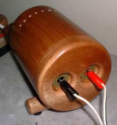
A completed Gainclone mono bloc And that's all there is to building what many people have hailed as a nice looking and unusual amp casing. What were the most difficult bits you may be asking. Cutting the heat sink was a bit fiddly with a jigsaw (using a metal cutting blade) due to the small size. I finished the shaping with a file. The front plates were a lot of work and as I have already said would be much easier to make on a lathe. I know somebody with a lathe and may ask them if they would turn me a few fronts for future projects. Other than that, nothing was too much of a problem given a little time and care and heaps of forethought.
A rear view of a Gainclone mono block.
|
|
OK, how many of you have clicked straight to this section?
|
|
Well, I have to say that from the moment that I connected up both channels and played some music through them I was totally astonished. I had tried to keep a totally open mind from the time that I decided to build a Gainclone in case I was disappointed after all my effort and expense. But I needn't have worried. And despite a number of people quoting a burn-in requirement, I found that my Gainclones sounded great from the first track I played.
|
|
The first thing that I noticed (and could hardly believe) was the huge amount of bass coming from these diminutive amps with the mere 2000 micro farads of capacitance. I had hooked the Gainclones up with my (very) old Mordaunt Short Pageant speakers (relegated to the store room about seven years ago after I built my first kit speakers). Cables were 79 strand copper (also made redundant many years ago) and the signals were provided by a bog standard Cambridge CD5 CD player that I had bought for 80UKP as a back-up for my CD723. A very cheap 100K pot in a box controlled the volume. I had never heard the speakers sound as good in the twenty years that I had used them.
|
|
Despite being a new and un-burned in pair of amps, the Gainclones sounded very smooth and airy and very, very euphonic. I had just put on a track to see if they worked after testing the DC offset and was not intending to test any further. But it was nearly three hours later that I could bring myself to stop listening and leave the room! Boy, was I a happy DIYer that night!
|
|
On further auditioning, I found the bass to be a bit flabby but put that down to the small squarish room, poor speaker supports etc. After trying some different (solid core) cables the bass has tightened up considerably although I seem to have lost some of the silky smoothness in the mid and high frequencies. Obviously more experimentation with cable is needed and I will also get a better idea of the Gainclones when I connect them to my main system.
|
|
And I also have to keep in mind that the sound will be changing as various components burn in. For instance, the Black Gate capacitors on the input are fairly new and I have been told by somebody who has used a lot of them that they sound awful at first, then good for about 80 hours, then worse again for about 200 hours before finally sounding their best!
|
|
One word of warning. I was checking the DC offset one morning and found that it had gone up to 285mV. I checked everything in the amp circuit and re soldered the joints to be on the safe side. When I reconnected the amp, I found that I had an offset of 34 volts! After assuming that I must have a faulty chip, and ordering some replacements, further investigating found that the negative supply rail measured 0 volts at the amp but -36 volts in the PSU. A wire had come loose in the umbilical from PSU to amp and reconnecting it solved the problem. It was lucky that I had decided to check the DC offset that morning of I would have destroyed a speaker. The moral of this story is that every component is important for reliable and safe performance. I had taken great care over the PSU and amp but been a little hasty in making what I considered to be a component of 'lesser importance'.
|
|
The only modification that I have made to the amps so far is to add 120 micro farad capacitors in the power supply. These tightened up the bass a bit, as did trying solid core speaker cable.
|
|
It is still early days with my Gainclones so I will be updating this pages as my experience with these little gems continues.
|
| Site menu
Page menu
|
|
|
I built these little amplifiers as an experiment, almost on a whim. However, the sound quality has got me considering whether to use them in my main system, replacing my modified Arcam A60's!
|
|
And if I do, what configuration should I use. I could just substitute them in place of the A60's where they would be situated immediately behind each speaker and driven from a pre amp. I am also developing a valve pre amp at the moment. But the Gainclones do seem to work well with nothing more than a 10K pot between them and a CD player although I may need to increase the gain to work with other components like the turntable.
|
|
I considered building both amps into a 'box' with the volume control and possibly a selector switch but that would be a waste of the lovely round cases that I am using now. An alternative arrangement would be to build a third (similar) housing for the volume control and place all three units in a row. I do have a third piece of veneered pipe already so that is a real possibility!
|
|
And how will the Gainclones sound with my Goodman's 201 speakers? I have been using my old Mordaunt Short speakers while I develop and test the amps so that if anything goes wrong, I'll only damage an old speaker and not one of my valuable 201's. But so far, apart from the problem with the broken wire in the power supply lead, everything seems OK and soon I will hook them up to the 201's. I do have some speaker protection units which I could use initially and then remove later when I am satisfied that all is well electrically.
|
|
Another option is to use my active system and build two more Gainclones so that I have an amp for each drive unit. Given the cost of the Gainclones, going active is much more of an option from a point of view of cost. I have an article from Electronics World magazine featuring some three-way active speakers using chip amps.
|
|
And if I don't use the Gainclones immediately behind each speaker, I will have to find the optimum speaker cables to use with them. I have already started experimenting and found that cables probably have a bigger effect on the sound of the Gainclones than on other amplifiers that I have used in the past. So, just when I thought that it was safe to put away the soldering iron, these little Gainclones have got me going again! BE WARNED - GAINCLONING IS ADDICTIVE!
|
|
UPDATE 23rd April 2003
After more experimenting with the speaker cables, I have found a twin flat-braided cable with a cross-section of 1.5mm² produces the tighter bass without affecting the quality of the mid-range and top end. I am still going to try the .4mm solid core that some people suggest for the Gainclones.
|
|
My opinion of the Gainclones just keeps growing with each new album that I try with them. Soon I'll be trying them in my main system to see what they can really do but I can tell you that my 22 year old Mordaunt Short Pageant speakers have never sounded anywhere near as good as they do hooked up to the Gainclones!
|
|
UPDATE 10th May 2003
I've been very busy lately but have now got two 18-0-18 transformers so that I can try the Gainclones with lower voltage rails. Some people have said that the sound is better with a lower voltage supply so I will test it for myself. And of course, having that second set of transformers means that I can build another pair of amps! Watch this space for a review of the 18 volt supply compared to the 24 volt.
|
|
UPDATE 24th May 2003
The soldering iron has been out again and I have slightly modified the circuit to reduce the DC offset. I replaced the wire going from the the non-inverting input (pin 7) to ground with an 18K resistor and added a 22K resistor from inverting input (pin 8) to ground. Click HERE to see the circuit diagram that gave me this idea. This reduced the DC offset on one amp to 0.4mV and the other to 4.5mV. (difference due to the variation in the chips). Listening after this modification, there is a very slight softening of the higher frequencies but this is possibly an improvement. The bass also seems slightly less prominent and more integrated with the rest of the frequency range. I may have to reverse the mod and see which sound I actually prefer and I also intend to try an alternative method of reducing the DC offset by using a 50K trim pot between pin 7 and ground.
|
|
UPDATE 3rd June 2003
I have been listening to my Gainclones powered from lower (27VDC) voltage rails instead of the 37VDC larger supply. The difference is quite small, at most I can detect a slight change in tonal quality. I wouldn't like to say which I prefer but if I was forced to make a decision, I would probably just favour the lower supply.
|
|
UPDATE 9th June 2003
Today, I removed the 18K and 22K resistors that went from pins 7 and 8 to signal ground. I put them there to reduce the DC offset (the original circuit had a plain wire between pin 7 and signal ground) of 28mV, to near zero. I now have 216K between the non-inverting input and signal ground, the DC offset is still zero but the magic sound of the original set up has returned. It is quite clearly a much better sounding arrangement!
|
|
UPDATE 22nd June 2003
I have now built the dedicated stepped attenuator using a 12 way switch and resistor values suggested by TL to work specifically with the inverted design. I have also completed a third 'pod' to house the attenuator as shown below.
GC stepped attenuator in matching housing
For those interested, I have described how I made the wooden knob (without a lathe) on the 'Building your own' page in the section on Casework and finishing.
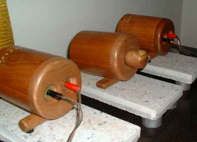
My Gainclone mono blocks with their matching volume control
|
|
UPDATE 20th July 2003
After a suitable period of testing and tweaking in my test set-up, I have now installed the GCs in my main system, fed by the CD723 and playing through my Goodmans 201's full-range speakers. The Goodmans are still running in after a complete rebuild earlier this year but already I have that big scale that large drivers produce. Vocalists are 'people' size! Bass is well-defined and should improve as the drivers break in. Mid-range and top end are silky smooth with no sign of the harshness that has sometimes been reported with a Gainclone. In fact the sound is more valve-like and less solid-state. Apart from breaking in the speakers, I can see that this system will be running overtime just to go through my CD and record collection!
BTW - with the 201's not long back from a complete rebuild at a cost of £120, I have played safe and connected one of the Velleman speaker protection modules between them and the GCs. I should point out that this is just for my peace of mind and I had no problems during three months of using the Gcs in the test system.
|
|
UPDATE 9th July 2006
I thought it worth reporting that a couple of years on, I am still using Gainclones to amplify my main system! And despite trying many variations, I prefer the simple inverted design described above but powered from the SMPS described here. These are used to drive my open baffle loudspeakers while another pair of IGC's (conventional linear power supply with 10K reservoir caps) power the transmission line woofers.
|
|
If you are becoming as hooked on the idea of chip amps as I did, then you will find the following links most useful.
My Gainclone FAQ/beginner's page.
My buffered Gainclone.
My valve-buffered Gainclone.
My Gaincloned Arcam A60.
DIYAudio form.
Chip Amp forum.
Fedde Bouwman's site including Gainclone amp .
Mark Hennessy's Gainclone.
Maarten's Geenkloons .
Craig Fraser's Gainclone amps .
Richard Murdey's Gainclone page .
Pedja Rogic's Gainclone page.
Jim Read's Gainclone page (+ matching TQWP speakers!).
Matthew Cattle's Gainclone page.
Tubes and Gainclones (Joe Rasmussen) .
Markku Poysti's LM3875 page.
47 Labs home page .
47 Labs chip amp review .
Final Labs chip amp review. .
A review of Peter Daniel's GC (a must read).
How OPAMPS work in plain English.
Marc Gautsch's Gainclone page.
|
| Site menu
Page menu
|
|
|

 The battery driven Final Analysis Music-6 chip power amplifier. With battery meter and damping control.