|
Decibel Dungeon
|
|
|
|
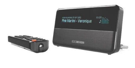
It seems that more and more audiophiles are moving to PC streaming for their source of music. Sound cards, USB DACs, and a host of other devices including the Logitech SB3 are only the start of things. The SB3 is very popular, rightly so as it offers a reasonable performance with a 'not-too-glitchy' interface that works fairly well. I bought one after reviewing the at-tunes SB+ that is based around the SB3 interface but manufactured to produce a much better sound. Having heard the SB+, and also the Slim Devices Transporter, you won't be surprised to know that I wanted to get more out of my SB3.
|
|
The analogue output of the standard SB3 is in my humble opinion OK. That is not really audiophile but fine for say background music in the kitchen. It can be improved, as companies like Bolder Cables have shown, but it is a lot of work. And working inside the very compact SB3 is no easy job. It was designed as a consumer item, and not for interfering tweakers like me to poke around inside with a hot soldering iron. So I decided almost from the start that my modifications would be restricted to the power supply and the digital output, and that I would use it with an external DAC.
|
|
Another problem with modifying the SB3 is a lack of any schematic. Slim Devices (who were taken over by Logitech) make a souped up SB3 called the Transporter so there was no advantage to them in releasing the schematic of the SB3 to help we tweakers. Despite that, some clever souls managed to decipher are least parts of the circuit and that opened the door for many of us to do some work inside the SB3.
|
|
The second stage of regulation down to 5 volts used another LM1084 regulator circuit identical
to the first except for the resistor values for UAR and LAR.
UAR is 240R in both cases with LAR being 1500R for 9v output and 750R for 5v output.
|
| Site menu
Page menu
|
|
|
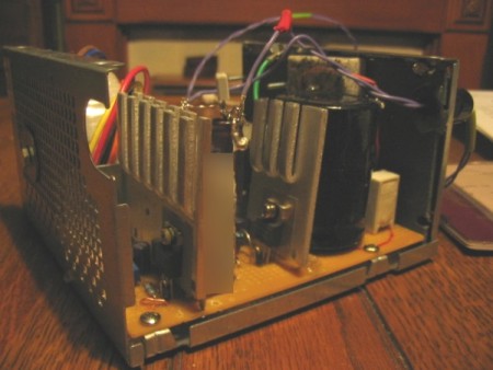
Almost always, if you ask about improving the SB3, the first answer is to improve the PSU. This is actually good advice and despite the doubting Thomas's who say that an external power supply can't make any difference to the sound because it all goes through a switcher inside the SB3, it does! You can spend any amount from a few pounds on a very basic linear power supply (the one that comes with the SB3 is an SMPS), to ridiculous amounts of nearly a thousand pounds. One of the best that I tried (for a review on TNT) was the SR1-5 from Paul Hynes supplies. I was pleasantly surprised at how much difference it made, but it does cost as much as an SB3. Well, this is a DIY site, so you won't be surprised to read that I built my own linear supply. Nothing really exotic, just two stages of text-book regulator circuits, one 8 volt and a second 5 volt supply. The supply was housed in a separate case (a gutted PC PSU case).
|
| Site menu
Page menu
|
|
|
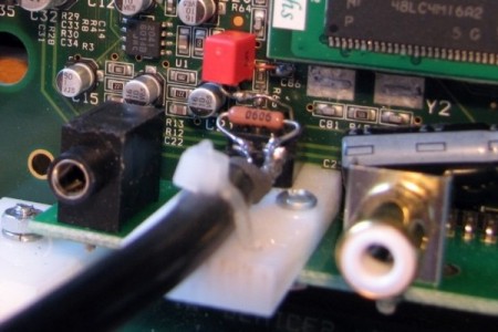
The next job was to modify the digital output section of the SB3. That job consisted of removing the small inductors L8 and L9 and then soldering an output pulse transformer in their place. The picture below shows this better than I can explain it. The transformer chosen was made my Murata (Farnell order code 1087809 ) and although it was quite fiddly, it went in without too much of a fight.
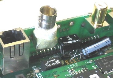
I then replaced the RCA socket with a BNC type as I firmly believe that the 75 ohm BNC connectors make for a better digital signal path. In this case, I removed the barrel of the RCA socket from its chassis and then cobbled the BNC socket onto the chassis, holding it quite securely with Milliput putty. I then had to drill out the hole on the rear of the original casework to accept the larger barrel.

|
| Site menu
Page menu
|
|
|
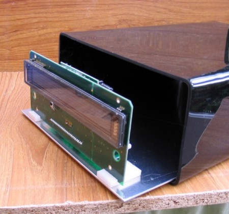
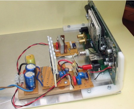
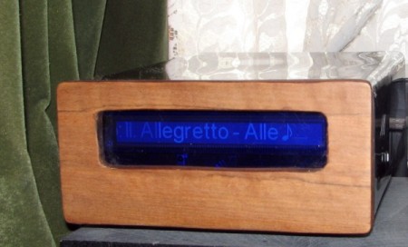
The case consisted of an aluminium tray, an acrylic sleeve, and a wooden front panel. If you want to try one of these, get somebody to cut and bend the aluminium for you. The 3mm thick acrylic can be bent at home using a block of wood and a hot air gun. I made up two brackets from thicker acrylic to attached the front panel too. The SB3 PCB sits in two more small pieces of plastic that have grooves cut into them to tightly hold the bottom edge of the PCB. If you take this route, you can buy BNC sockets,and an RJ45 socket to extend those connections to the rear of the new case.
|
|
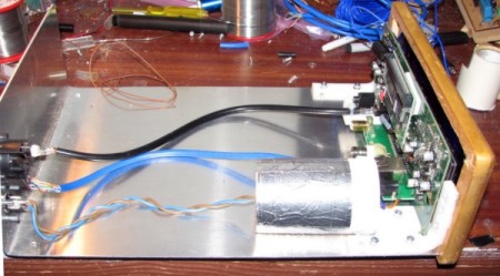
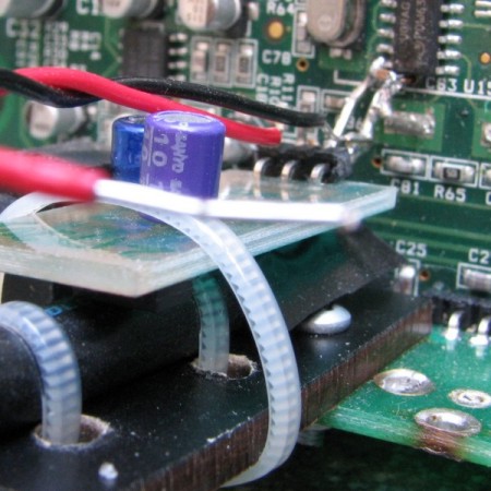
Sometime later, somebody suggested a complete rework of the SB3 digital output and I changed my circuit accordingly. The originator of these mods suggested using a miniature 75 ohm coaxial cable to connect the output of the digital output to the output socket. As this was almost impossible to source (without buying a 100 metre roll) I decided that this was the time when I decided to build the new case. You can see below how I used an ordinary sized coaxial cable to connect directly to the digital output circuit. It's clamped in position otherwise any movement would break the very flimsy connections to the tiny SMD components on the PCB.
Full details of this modification are discussed here on the AudioCircle forum but don't rush out and do them just yet. The thread was started by Pat of AnalogueResearchTechnology who pointed out that if the mods were not done properly, they probably wouldn't result in better sound quality. There's a lot more to messing with digital circuits than meets the eye.
|
|
Well you know in hi-fi tweaking not everything is necessarily a step forward! After initially thinking that the sound was better with the digital output mod, I had a chance to hear another SB3 with the standard output and decided that I liked it better! So, I put things back to how they were, except that I still took the coaxial cable directly to the output stage, cutting the original tracks to the onboard output socket.
|
| Site menu
Page menu
|
|
|
Another tweak is to remove the second crystal (Y2) inside the SB3. First of all be warned that if you do remove this crystal, it will stop you replaying 48KHz (or subdivisions of 48KHz) audio files. You also won't be able to stream internet radio. I've actually removed this crystal in two SB3's now. One came out very easily, the other needed a bit more effort and perseverance. I heat the pad at one end of the crystal and try to try up the crystal using a tiny jeweler's screwdriver tip. Removing this crystal does make a small improvement to the sound quality. I would also like to add something from another SB3 tweaker though.
A word of caution about removing the 2nd crystal....
Some time back I proposed this as a possible SQ tweak, however I was warned that some internet radio stations (32kHz sampling freq???) can cause the SB to output white noise at full o/p. I had to try many stations but eventually proved this was true and the o/p noise was at a very higih level indeed - even if it does not blow your speakers it could give you a heart attack, especially if the SB is direct into a power amp (obviously mine wasn't for the purposes of the experiment).
Because of this I refitted the crystal. When I first removed it I thought the sound was better, when I put it back I could not detect any difference. Ah the joys of tweaking!
Of corse if you have no intention of streaming internet radio the above won't apply, and if you need the phyisical space, then it has to come out anyway. Yes, as he says, "the joys of tweaking!"
Also note that to do this job, it is best to remove the daughter-board from the main PCB of the SB3. Be very careful how you do this as the socket is quite flimsy! Try and remove it by pulling it away from the main PCB and keeping it square as you do so.
|
| Site menu
Page menu
|
|
|
Going back to the power supply, I decided to try and separate some of the circuits. Initially, with the new case, I moved the second stage of regulation (in the plastic pod) to the SB3 case keeping it as near to the input socket of the SB3 as I could.
There's always some gain to be had by providing different circuits with their own power supply. Again, a lack of schematic meant that this job wasn't straight forward. It was very much a case of poking around with my meter, seeing what was connected to what, and at what voltage. Eventually, I came up with a plan. The five volt supply would still be fed by my five volt regulator. I would lift the output tabs of the internal 3.3v regulator (U8) and replace it with another linear regulator based on the LM1084 that I had used for the other regulator circuits.
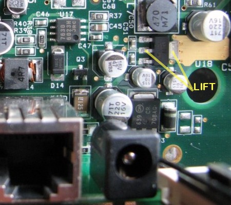
I would then cut off the supply to the digital output chip (HCU04) and supply that directly from another 3.3v regulator. The HCU04 draws hardly any current so I used an LM1083 regulator for that.
|
|
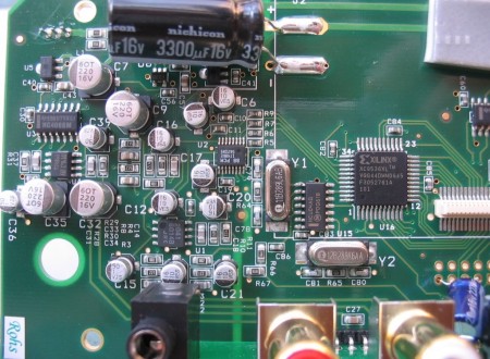
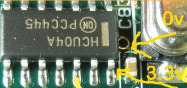
The supply to the HCU04 is cut by drilling out a via (the one marked 3.3v in the picture). But be warned, the HCU04 is immediately behind that via so don't use an electric drill, or Dremel. Hold a tiny twist drill with a pair of pliers and twist it carefully until you go right through the via. You can check that the supply is cut by using your meter to check that there is no continuity between the power supply pin on the HCU04 and the output of U8 (on-board 3.3v regulator).
|
|
I would have liked to have supplied a dedicated power supply to the Xilinx chip as well but just couldn't work out how to isolate it's supply as it has more than one. Anyway, this is how the new power supply looked.
with the circuit looking like this.
UAR is 240R in all cases with LAR being 750R for 5v output and 390R for 3.3v output.
|
|
Anyway, I felt that the new triple-regulated supply made quite an improvement and was happy to live with it. To be honest, I'm not sure how much difference using the external 3.3v regulator makes over the original SMD one. But it certainly didn't make things any worse so I left it as it was. If you don't want to lift the tabs on U8, it probably won't make a shed load of difference to keep it as it is. On the other hand , if you do want to add an external regulator to replace U8, make sure that it can supply enough current, ie around 200mA. Also please note that if you feed the main 3.3v supply from an external regulator, you bypass the voltage protection built in to the SB3 (that shuts it down if too high a voltage is supplied to it). So you must be confident that your 3.3v reg doesn't put out any higher voltage.
|
|
So, it appears to be the addition of the separate supply to the HCU04 that makes the biggest improvement and I was quite pleased with he triple regulated SB3! That was until I was offered one of Paul Hynes 3.3v shunt regulators to try on the HCU04. It was no easy job getting the PH reg in place but I managed to solder its output leg directly to the pin of the HCU04. Once again. I was careful to physically secure the regulator to minimise any stress on the soldered joints. The tiny SMD cap that you can see in the picture is the one originally soldered to the PCB next to the HCU04. I mistakenly took this out originally and getting it back in was a nightmare. You won't need to do that. The 0v pin of the PH reg is soldered to a very short length of bare CAT5 solid core wire that is first soldered into the 0v via at the bottom side of the HCU04. Paul Hynes had recommended a completely separate power supply for his regulator, ie new traffo, rectifier, smoothing cap etc, but as I didn't have a suitable transformer when I installed the regulator, I simply connected it in after the existing 3.3v regulator that was converted to output 6 volts by changing the LAR to 910R. So now the HCU05 has three stages of regulation. I will try the separate supply when I get hold of a transformer and if it makes further improvement I will be very pleased as it sounds so good now.
|
|
What you can't see in the picture above is that when the daughter-board is replaced, it actually touches the PH reg so there is absolutely no room to spare. If you do this mod, make sure that there is room for everything to go back together! Anyway, a rather tortuous job paid dividends big time. The transformation was quite amazing and way in advance of anything else I had tried with the SB3. For the first time, I felt that the SB3 was on a par as a digital transport with the Transporter, although by this time it was quite a while since I had the latter in my system so I couldn't swear to that. Anyway, I recommend these power supply modifications, using the Paul Hynes regulator without reservation.
|
|
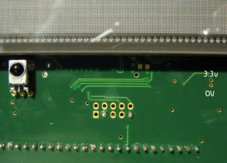
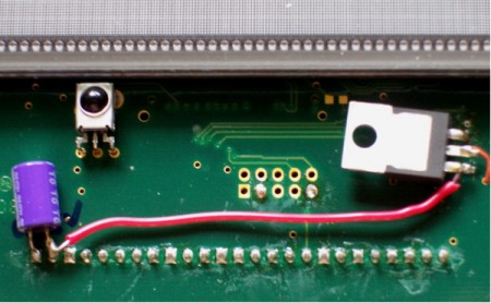
Yeo, of DiyParadise found another way to install a separate regulator for the HCU04, without the need for a larger case. The supply is taken as shown in the picture below and comes directly from the 5v input to the SB3. The supply to the HCU04 is connected with the thin red wire going through the via.
|
| Site menu
Page menu
|
|
|
I would still like to connect a DAC to the SB3 using I2S, but as for modifying the SB3 as a digital transport, that will probably be as far as I go. Of course, if I do do anything more, it will get written up here. I hope that this article will encourage you to improve your SB3 but be careful, it is a fragile device to work on. The information above is accurate, and provided in good faith but I can't take any responsibility for any mishaps. That said, with the appropriate care, you shouldn't come to grief! If you have read all through this page and feel it is a bit too much work, let me summarise what will get you the same performance with the minimum amount of work:
- Build larger case.
- Build new linear 9v PSU.
- Add 5v regulator right next to SB3.
- Cut track from R67 to output socket.
- Solder new coax cable from R67 and nearby ground via to output BNC socket in new case.
- Drill out via to HCU04.
- Add Paul Hynes 3.3v shunt reg to HCU04 fed by 6v regulator stage.
- Sit back and enjoy.
|
| Site menu
Page menu
|
|
|