|
Decibel Dungeon
|
|
|
|
The 'speakers for this project are built around drive units made by Audax. The woofer is the 170mm HD-A cone driver with a cone made from High Definition Aerogel, which Audax claim 'surpasses all conventional materials'. This is a quality drive unit as reflected by a price of about 50UKP. I have been using these drivers for over three years now and recommend them unreservedly.
|
|
The 25mm soft dome tweeter is also an Audax creation and is model number TW025M1. Audax claim it has a replaceable voice coil assembly but I have yet to find anyone who will supply one in the UK, including the main distributor. That aside, this is a good quality tweeter for the price of 16UKP and matches the Audax woofer well when used with the active crossovers used in this project system.
|
|
For a supplier of Audax drive units in the UK, go to the IPL Acoustics. site.
|
| Site menu
Page menu
|
|
|
If you have got this far you will be pleased to hear that this is probably the least complicated part of the project. Normally, the biggest problem with building a 'speaker is designing and building the crossover but as we already have active crossovers, the only work involved is building the 'boxes' and installing the drive units.
|
|
The system as described so far could be partnered with many two way 'speakers and work quite well. However, the design which follows has been developed as an optimum match and has been built and tested rather than just worked out in theory. You don't have to build exact replicas of the cabinets described below but any alternative designs should have the same internal volume, 31-32 litres and roughly the same port size. I say roughly because you may find that a slightly different size of port works better in your listening room but don't worry, I'll be describing how to make any alterations.
|
|
I should point out that these speakers were originally supplied with an IPL A2 kit, with a suggested ported cabinet design of 27 litres. However, in their excellent guide to active loudspeakers, Falcon Acoustics make the following point.
Quoted from 'Active Loudspeaker crossover filters and sub-bass' 3rd edition by Falcon Acoustics Ltd.
"One point that is usally forgotten or unknown is the change of bass alignment with the removal of the bass inductor
In I.B. enclosures this is usually not too much of a problem, the the system QTC being reduced and the system being nearer to a Bessel roll-off than a Butterworth. This can give the impression of a tighter, if slightly less, bass. However if the system is designed to give the impression of a lot of bass by making the system 'Q' high [QTC>0.8] then the reduction can dramatically improve bass quality.
Reflex enclosures are much more of a problem as the tuning can be greatley affected, with not only the port needing changing but the cabinet volume - usually larger!
Hence the bass cabinet may, and probably will, need to be redesigned for optimum performance."
|
|
The cabinet design is based on my experiments with my own 'speakers over a period of three years. The volume is based on trial and error usig the drivers with the active, rather than the passive, crossover. As I had access to free offcuts of MDF and blockboard, I have been able to build a number of different designs. This has enabled me to listen to the differences (if any) of changing the position of the reflex ports, using front baffles of different widths, using various damping materials and cabinet shapes. You can read as much as you like about these subjects but there is no substitute for the 'hands on' approach.
The INTERIOR dimensions for the cabinet shown in the diagram above are:
- Height H = 560mm
- Width W = 240mm
- Depth D = 330mm
- Triangle side 1 X = 150mm
- Triangle side 2 Y = 150mm
- From top to centre of cutout Z = 75mm
As you can see, the shape is basically a box 560mm by 240mm by 330mm with a triangular block removed from its top rear. The idea of the sloping rear panel is to deflect the sounds waves coming from the rear of the 'speaker cone downwards instead of having them reflected back to the cone. The cone materials of modern drive units are often very lightweight (like HDA) and it is best to minimise the amount of out-of-phase sound which escapes through them.
|
|
The exterior dimensions will depend on the materials that you choose to build the cabinets from. I do recommend a combination of 12mm chipboard bonded to 10mm insulation board (which goes on the inside). I construct the front baffles from two layers of chipboard which have a 25mm gap which is filled with dry sand. This gives exterior dimensions of 605mm (H) by 285mm (W) by 390mm (D). The tweeters in this design have their own separate housings and sit on top of the woofer boxes. These in turn sit on matching stands which bring the drivers to the correct height for listening while you are seated. Note the aperture for the port in the centre of the base panel. Cut this to suit whatever pipe you choose for the port.
|
|
I'm not going to describe how to build the cabinets. Everyone has their own preferred methods and this is not a DIY carpentry site. Suffice to say that you should ensure that you have plenty of bracing (I prefer a combination of shelf-bracing and cross-bracing) and that the cabinets are sealed airtight with something like silicon sealant. Allow plenty of time for the adhesive and sealant fumes to dissipate before you install the drive units. See the Loudspeaker building section for further construction tips including an easy way to 'rebate' the woofers.
|
|
As regards damping, I use layer of carpet on the top panel and a double layer on the sloping panel behind the woofer. I use any type of foam material that I can find for the sides of the cabinet and the vertical rear panel. I once bought a large piece of foam with the 'egg-box' profile which was sold originally as a mattress. This large piece of foam cost me just 2UKP in a charity shop.
|
|
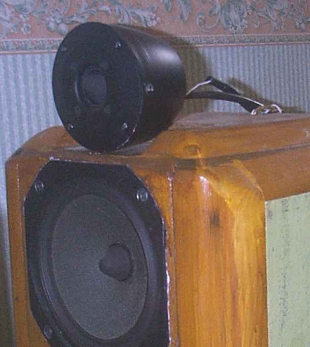
There are several options for housing the tweeters. Here are three suggestions:
|
|
Whichever method you use, you will be able to adjust the position of the tweeter in relation to the woofer in order to get the best time alignment. The distance involved may seem too small to be of consequence but it is the attention to such small details as this which separates good hi-fi systems from great ones.
| TIME ALIGNMENT - sounds from the woofer and tweeter must arrive at your ears at exactly the same time which they won't do if they travel different distances. Due to their different physical sizes, the drivers do not emit sound from the same vertical plain but moving the drivers in relation to one another allows the points at which the sounds originate to be aligned.
|
| Site menu
Page menu
|
|
|
|
|
|
|
The stands are made from pieces of MDF or blockboard. You will require the parts shown in the diagram above. The small rectangle is the same size as the base of the cabinets, the larger rectangle about 50mm larger all round. The dimensions and shapes of the 'leg' pieces are not critical but when the stand is assembled it should raise the 'speaker' about 180mm off the floor. The position of the 'legs' is marked by the lines bisecting the corners. I fit adjustable spikes to the bottom of my stands and use small 'squidgey' balls between the stand and cabinets.
|
| Site menu
Page menu
|
|
|
I have used plastic drain pipe for my ports. It's very cheap as I usually manage to beg some scrap pieces from building sites. It has an internal diameter of 65mm and after some measurement and a bit of trial and error I arrived at a length of 105mm. This works very well in MY room but you may need to make slight adjustments to suit your own room. To make this easier I suggest that you have some method for removing the ports from the cabinets in order to change their length. The method I use is to make up a circle of MDF about 80mm in diameter with a hole in the centre into which I glue the port. I then insert the port and flange into the cabinet and hold it in place with two screws. I use Vaseline to form a(breakable)seal between the flanges and the cabinets. Of course, you can make things less complicated by buying a pair of adjustable ports!
|
|
Mounting the port for easy removal.
|
|
If you want to use a different diameter port, here are some alternative diameters with the appropriate length to tune them to 38HZ.
|
| Diameter | Length |
|---|
| 50mm | 80mm |
| 75mm | 130mm |
| 100mm | 390mm |
|
|
I don't like using ports with a diameter less than 50mm as this can cause the air being pushed through them to 'chuff'. I have actually heard this on a 'speaker with a 25mm port mounted on the front baffle.
|
| Site menu
Page menu
|
|
|
What finish you choose for your 'speakers and stands is up to you depending on how much time and money that you are prepared to spend.
|
|
The drive units are installed in their respective enclosures using T-nuts and bolts for the woofers and screws for the tweeter. The best place to have the power amplifiers is just behind the 'speakers and I do that by housing the amplifiers in a box on the wall. See the positioning hi-fi section for an illustration. With the drive units so close to the amplifiers, you can consider soldering wires directly to their terminals and running them directly to the output terminals on the amplifiers. I route the wires from the woofer through a hole in the top of the cabinet and along a groove. A wooden 'plate' is screwed over the hole and groove which compresses some plasticine to make an airtight seal. The wires for the tweeter already emerge from the tweeter housing.
The exit hole through the top of the cabinet is sealed with plasticine (shown in blue).
|
|
And that is the 'speakers section more or less completed. To conclude the Decibel Dungeon project, I'll soon suggest some interconnects that work well, and tips for getting the best performance from this system.
|
| Site menu
Page menu
|
|
|