|
Decibel Dungeon
|
|
Reproduced from an article in ETI magazine, January 1988.
|
|
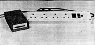
Paul Chappell's mains is close-up clean thanks to this top spec and remarkably attractive power conditioner.
|
|
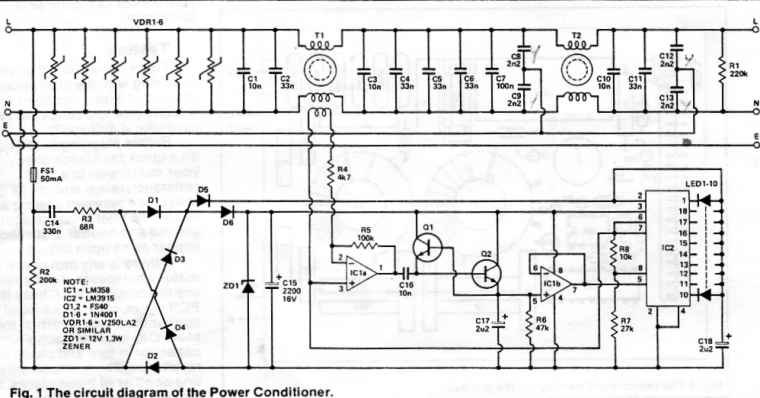
Click HERE for the circuit diagram.
|
|
How it works
The filter section begins with six VDRs, which are Intended to remove the damaging effects of high energy tran-sients on the mains. To some extent they will reduce Impulsive Interference effects loo but will not eliminate them.
|
|
The filter section will remove RF Interference from the power lines. The current balanced inductors in com-bination with the Y-capacltors (08, 9, 12,13) serve to clean up common mode Interference, while the X-caps (C1-6, 10, 11) do the same for differential mode noise.
The current balancing in the toroids prevents the cores from saturating under the effects of the current drawn by the load.
|
|
The pick off coll from the first toroid detects any imbalance caused by interference currents flowing to ground via via (he Y-capacitors. The signal is amplified by IC1a and passed to the detector circuit consisting of Q1 and 2 and associated components.
|
|
This detector responds to the peak value and to the duration of the signal, so a short, high voltage pulse wfll give the same reading as a sustained, low amplitude burst.
|
|
IC1b feeds the detected voltage to IC2, which is a common or garden bar-graph drive 1C.
The LEDs are fed with current pulses from D5 to reduce the overall current consumption of the circuit and dissipation in IC2. The 1C is switched to dot mode twice each cycle of the mains (via pin 9) to reduce the current requirements still further.
|
|
If you look closely at the display, you might just discern a difference in brightness between the highest dot and the rest of the bar but the overall effect is of a continuous bar display.
|
|
The power for the low voltage circuit is derived from the mains via C14. R3 prevents damaging inrush currents If the mains happens to be close to its peak value at the time the circuit is switched on.
|
|
R2 provides a discharge path for C14 when the conditioner is disconnected from the mains or if the fuse should blow.
|
|
This kind of power supply does not isolate the low voltage circuit from the mains and is only suitable for use in completely self-contained pieces of equipment like the conditioner. The supply capacitor will be large but nowhere near as bulky or heavy as a mains transformer for circuits requiring small currents (up to 100mA or so).
|
|
A capacitor used In this way should be X-rated since it is effectlvely connected across the mains.
|
| Site menu
Page menu
|
|
|
Year by year the pollution of the mains supply grows steadily worse. In addition to the usual industrial effluents from rotating machinery, waste products from switch mode power supplies, sewage from drills, washing machines, vacuum cleaners and oven thermostats, there are now plans afoot to pollute the mains deliberately.
|
|
I hardly need to mention the consequences — streaky TV pictures, popping and crackling radios, mushy hi-fi sound. Greenpeace — where are you when we need you?
|
|
Mains borne interference is not a thing to be taken lightly. Spikes of 1 kv and above are a common (in some areas frequent) occurrence and this can and does damage unprotected equipment. A simple voltage dependent resistor (VDR) connected between live and neutral of the mains plug will usually forestall damage to the equipment but it doesn't prevent the annoying interference effects.
|
|
Apart from spikes and impulsive interference, there is a constant background of more regular interference which gets steadily worse as time goes on. RF interference has become more of an annoyance since the CB boom and the increasing use of switch mode power supplies adds its own contribution. The latter are supposed to be suppressed at source but this only serves to reduce the interference and doesn't eliminate it.
|
|
Another development has been the increasing use of the mains for signalling purposes. At its lowest level this can be equipment such as cordless intercoms but the problems associated with sending digital signals through the mains are rapidly being overcome.
|
|
Some years ago National Semiconductors introduced the Bi-Line system, the front end of which was an IC (the LM1893) which puts data through the mains by means of an FSK modulation system. It was, by its nature, for localised use but this and similar systems — even the home computer add-ons for through the mains control — are all adding to mains borne interference.
|
|
A system to eliminate gas and electricity meter readers has now reached the stage of field trials. The idea is that meter readings are sent via the mains as far as the nearest sub-station, from where they will be transferred to the telephone lines by means of a modem.
|
|
This long distance use of mains signalling obviously can't be suppressed, so a band has already been set aside for it. One can envisage a time when the 'mains waves' will be just as strictly regulated (and just as crowded) as the air waves. The effects on hi-fi and audio equipment have yet to be seen.
|
|
In addition to all this man-made interference, there is another source which will always be beyond any kind of legal regulation and control — the weather. Electric storms and even lightning strikes make their presence felt through the mains.
|
|
The only way to be sure of an unpolluted power supply for your audio equipment, TV or computer is to clean it up yourself. The ETI power conditioner is the tool you need for the job.
|
|
Inside the conditioner the mains supply is purified, transients are cleared and RF interference is blocked. The clean supply is then fed to a socket or multi-way outlet which can supply power to all your sensitive equipment.
|
|
If you find it hard to believe that the mains is really as polluted as I say, this project will certainly convince you. A unique feature is its bar graph display which actually lets you see how much interference it is removing.
|
|
As you watch the LEDs move and occasionally flick way up towards the top of the scale, you'll be in no doubt that the power conditioner is working for its living.
|
| Site menu
Page menu
|
|
|
The correct way to avoid any problems with mains connections the gospel goes is to plate all your plugs with gold. The reasoning behind this was explained to me by the proprietor of Hi-Price Audio to be something like this:
|
|
The gold plating on the plug acts very much like the uniform of the doorman at the Dorchester
Hotel. Nice, well-bred sine waves know that they will be welcome inside, whereas interference is overawed By the golden splendour of the doorman's uniform and embarrassed by its own scruffy appearance. It knows that it will feel out of place in such magnificent equipment and wanders on in search of the electronic equivalent of a Yummy Eater fast food bar.
"Besides," he said. "if punters ; fink they can hear a difference, am I going to argue?" I was impressed by his logic and bought a dozen.
|
|
Of course, back in the real world we have a mains filter which works to consider.
|
|
|
|
The filter begins with six VDRs. This is partly a concession to the fringe hi-fi community who believe that if one is good, six must be six times as good. For a given spike, the clamping voltage will be reduced by an infinitesimal amount by having a number of VDRs In parallel, due to the highly non-linear voltage to current relationship of these devices.
|
|
It's rather like hoping to reduce the forward voltage drop of a diode by wiring half a dozen in parallel. It will be reduced very slightly but not so's you'd notice the difference.
|
|
For more rational beings, there is another reason for having half a dozen VDRs. A VDR will only absorb a certain amount of energy from a spike before becoming stressed beyond its limits. If these limits are exceeded, it can result in the VDR breaking open and scattering zinc oxide far and wide. After that, your equipment is no longer protected.
One of the essential figures on a VDR data sheet is the maximum energy it can absorb in a short period of time. Figures of 5 to 20 Joules in 10ns are common for small components. To increase the energy you have the choice of buying a larger VDR or using several in parallel.
|
| Site menu
Page menu
|
|
|
The parallel option has the advantage that you can choose how much protection you want to give (an upgradable mains filter!) and that the average absorption over a longer period of time will be greater than for a single large VDR.
|
|
It could be that because of an electric storm you get just the conditions to pop a large VDR (and your equipment) but which would allow the parallel combination to continue giving protection. Speaking as one whose new TV set has just been zapped by a thunderstorm which exploded the plug VDR too, the more protection you can give, the better.
|
|
For those of you who are not familiar with the characteristics of VDRs, they are rather like AC versions of the zener diode, although the voltage clamping is not so sharp. Below their rated voltage they are virtually an open circuit. A little above this they begin to conduct until at about twice the rated voltage they have virtually no resistance at all. It may seem that a sharper cut-off would be an advantage but too quick a conduction would lead to blown VDRs every time there was a long term surge in the mains voltage. They are, in fact, very well suited to their job.
The clamping voltage is usually measured at 100A and will be somewhere between 600V and 800V for a device rated for 240V mains operation (which will begin to conduct at about 350V — just above the mains peak). The peak current for even a small VDR will be many hundreds of Amps but this can only be sustained for a few microseconds.
|
|
High peak currents for a very short time is exactly what impulsive interference will give.
|
| Site menu
Page menu
|
|
|
The main section of the filter consists of a pair of current balanced inductors and banks of capacitors to remove RF interference. A number of capacitors in parallel are used in preference to a single large capacitor to take advantage of the much higher self resonant frequency of the smaller caps and also because they are generally able to withstand short term thermal and voltage overload better than their larger brothers.
|
|
The value of the capacitors to earth is limited by the need to comply with earth leakage regulations — they are the maximum allowable values, taking into account their tolerance and should not be increased under any circumstances.
|
|
Connecting capacitors across the mains puts them under enormous stress and components not designed for the job can easily catch fire, short circuit, or at best just quietly fail — even if the voltage rating is high enough.
|
|
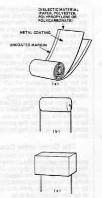
The basic construction of a metalised film capacitor.
(a) The two strips of metalised film are rolled together.
(b)The ends of the roll are coated with metal and the leads welded on.
(c) Finally the whole assembly is dipped or encapsulated to give the capacitor you buy from your component supplier.
|
|
Capacitors which have been designed to withstand the stresses and to comply with the appropriate standards are divided into three main categories: Class X1 These are for connection between live and neutral in situations where pulses of over 1.2kV can be expected. Class X2 These are for connection between live and neutral where transients will not exceed 1.2kV. Class Y These are made to the highest standard of all and are used for connection between a power line and earth or any other situation where failure might expose someone to a lethal shock.
Most capacitors for mains use have the rather magical sounding property of self-healing. This is a consequence of the metallised film construction, the essentials of which are shown in Fig. 2.
The dielectric material is coated with a very thin layer of aluminium — around 300 Angstroms (3 x 10^8 metres) thick. Two dielectric strips will be coated — one with a margin on the left hand side and one with a margin on the right. The two will then be wound together so that the metal film of one 'plate' extends to one side of the roll and the other to the opposite side.
|
|
To make the connections, the two sides of the roll are sprayed with metal from a flame or arc gun and the leads attached.
|
|
You can see this kind of construction in the 'naked' metallised polyester capacitors — the block shaped ones with metal at either end and leads that fall off at the slightest provocation. These caps are layered in long strips and then sawn up into individual capacitors rather than being individually wound, but the principle is the same.
|
|
The difference between class X and Y capacitors and the cheap 'n' cheerful metallised types is mainly in the standard of construction. The mains capacitors may be interleaved with paper (sounds an odd material but it has some excellent properties), be vacuum impregnated with epoxy to remove air pockets where ionisatlon may take place, be series wound to reduce electrical stresses, have several layers of bonding metal, be encapsulated in fire retardant material and so on. Construction varies from manufacturer to manufacturer.
|
|
If the dielectric is punctured by a high voltage spike, instead of short circuiting through the carbonised mess left behind when the dielectric burns, the very thin metallisation is vapourised away from the area and the capacitor carries on as if nothing had happened!
Strictly speaking, the metallisation is oxidised, the oxygen being supplied by the decomposition of the dielectric. The oxide doesn't conduct, so the damaged area is sealed off. It's not quite self-healing but almost as good!
|
| Site menu
Page menu
|
|
|
|
|
|
|
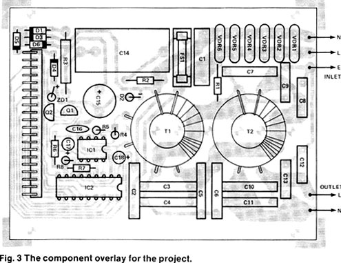
The component overlay for the project is shown above. Some of the components are mounted vertically to save space — the leads should be bent carefully and not too close to the body of the component to avoid stressing the bonding.
|
|
The best way is to hold the lead just above the component body in a pair of pliers, then to bend the lead in a smooth curve with finger and thumb.
|
|
The VDR positions have two holes for the 'live' connections, allowing components with either a 0.2in or 0.3in lead pitch to be mounted. Similarly, the capacitor which supplies the low voltage circuit has two pads for one of its connections to allow two popular sizes of capacitor to be mounted. The remaining hole is left unused.
|
|
Each coil on the two toroids has 15 turns of 1mm diameter enamelled or the circuit will not work properly. In addition to the power windings, T1 has a further pick-off coil of 15 turns of 0.25mm diameter wire over the centre of the coil in the neutral line. This connects to points A and B on the circuit board. The direction of this winding is not important.
|
|
The 1 mm diameter wire is firm enough to support the toroids on its own (in fact, you'll need quite strong fingers to wind it into a neat coil) but holes have been provided on the PCB for strapping them down with cable ties, just to be sure.
|
|
Figure 4 shows details of the inlet and outlet cables and connections. A 2BA bolt and solder tag is used to earth the metal chassis of the case and to provide a connection point for all the earth wires. Strain relief grommets must be used on the panel cable holes to clamp the leads firmly in place.
|
|
The front panel is drilled with a line of holes at 0.2in intervals for the LEDs. I used 3mm round red LEDs in the prototype but there is no reason why you should not use other shapes or colours if you wish. The usual black mounting clips can be used but they will have to be pared slightly with a sharp knife to fit the 0.2in spacing of the holes. Otherwise, you may prefer the appearance of the LEDs without clips.
|
|
Whether or not the clips are used, the LEDs should be stuck in place with epoxy resin so there is no possibility of the leads touching the panel or slipping through and becoming exposed.
The low voltage section of the circuit is not isolated from the mains, so for safety purposes must be thought of as being live.
|
|
When the LEDs and the inlet and outlet cables have been attached to their respective panels, you can solder the power connections to the PCB. The LEDs are best left unconnected until the case has been assembled, otherwise you won't know how short to trim the leads. Screw the chassis together, with the PCB resting on the bottom flanges of the side pieces. Turn the whole assembly over and check that there is enough clearance between the metal flanges and the pads and tracks of the PCB. Check also for solder blobs, untrimmed leads or any swarf on the flanges that might cause a short between the metal and the PCB tracks.
|
|
When you are sure that all is well, fit the chassis into the bottom section of the case and screw the PCB to the support pillars. The LED leads can now be trimmed to size and soldered to the header pins on the PCB.
All that remains is to put in the fuse, screw down the lid of the case, press in the rubber feet and your Power Conditioner is complete!
|
|
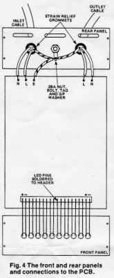
The front and rear panels and connection to PCB.
|
| Site menu
Page menu
|
|
|
There is very little that could be wrong with the filter section of the circuit except for open or short circuits (you did check the PCS carefully, didn't you?)
|
|
Before plugging in, it's best to do a quick resistance check. Set your multimeter to a high resistance range and check the resistance between ground and live on the inlet lead, then between ground and neutral. Both should appear as an open circuit.
|
|
If there is any movement of the meter whatsoever, don't attempt to use the conditioner. Check the PCB again, check your input lead connections and if both of these seem OK, take out each Y-capacitor in turn and check its resistance. The fault can only be in one or other of these places,
so you won't have far to look.
|
|
A resistance measurement between live and neutral on the inlet or outlet lead should show up a resistance of about 220k — the discharge resistor. If it is much below this (say, below about 180k, which could just be the result of resistor tolerance and meter Inaccuracies) take out the fuse to the low voltage circuit and see if this makes any difference.
|
|
If not, check the PCB carefully and as a last resort check the resistance of each of the X-capacitors. A final possibility — if you've damaged the coating of the copper wire on the toroid coils and allowed the two coils to touch (I hope not!) this will also cause problems (to say the least!)
If all is well so far, check the continuity of the live, neutral and particularly the earth connections. (Check the resistance between the input earth and output earth and make sure it's zero and so on).
|
|
After making sure that there is a suitable fuse in the plug, apply power to the conditioner but don't plug anything into the output socket yet. You should see the LED display flick upwards as you turn on the power, then the LEDs will go out one by one until they are all extinguished. If you keep watching the display for a while, you'll probably see it flick upwards every now and again as the conditioner catches some interference. Even with nothing connected to the output, it still removes pollution and gives an indication of how much there is around.
|
|
If all the LEDs light up and remain lit, don't instantly conclude that there's something wrong. Take a look around and see if you can find anything that might be causing a lot of interference.
When I first tested the prototype in the ETI lab, all the LEDs lit up and I spent several minutes puzzling what could be wrong — everything seemed OK. Then the photocopier in the next room stopped printing...
|
|
Now is the time to find out how good a job you've made of winding the coils. Plug your hi-fi, TV set or whatever into the outlet socket and take another look at the LED display. The sensing circuit will always pick up a certain amount of 50Hz signal from slight imbalances in the inductor and from slight differences in the Y-capacitor values, but it should not be enough to swamp the display.
|
|
If most or all of the LEDs remain lit ten seconds or so after plugging something into the output socket, there is a good chance that you have one turn too many or too few on one of the coils.
|
|
If one or two LEDs remain constantly lit, you can improve matters by adjusting the coils (or ' re-winding them if they're untidy!) or as an absolute desperation measure the value of R5 can be reduced to bring the display into line. The heavier the load, the more apparent any imbalances will be — an electric fire makes a good test load.
|
|
If the display section does not seem to be working properly, don't attempt to test it with its capacitor power supply. Remove all connections from the mains, set your bench power supply to about
16V, connect the negative lead to the negative lead of C15 and the positive lead to the junction of C14 and R3. Connect the negative lead of the multimeter to the negative terminal of your power supply.
|
|
Check the voltages on pins 9 and 3 of IC2. Both should be 12V (or within 1V either way). If both are higher, ZD1 is probably faulty.
|
|
If only one is higher, check D5 or D6. If either or both are low, disconnect the power and check all the diodes (in particular, check they are the right way around).
|
|
Also check C15 and C18 and the PCB for shorts. If the readings are OK so far, check the voltage at pins 6 and 7 of IC2 and pins 1,2 and 3 of IC1 They should all be the same at about 6V. Touching a finger to pin 2 of IC1a should cause all the LEDs to light. Remove the finger and they should turn off one by one.
|
|
If this works but the display doesn't seem to pick up anything from the mains, check R4 and the connections to the pick-off coil.
|
|
If nothing happens at all, measure the voltage at the positive plate of C17 and see if it rises when you touch the 1C pin. If not, check for a short in C17 (or a solder blob across its pads!) and the connections of 01, 02 and C16.
|
|
If the voltage across C17 rises, but the LEDs don't light, check the voltage at pin 5 of IC2. This should also rise. If not. IC1 is faulty. If it does rise but the LEDs don't light, check all the connections around IC2 and replace it if necessary. If the voltage across C17 remains high at all times (without the finger), suspect 01, 02 or C16.
|
| Site menu
Page menu
|
|
|
In the form presented so far, the Power Conditioner can be used with loads of up to 1.5kW. It will, in fact, cope with loads of 2kW intermittently — I tested the prototype by running it for an hour with a 2kW electric fire as a load. It didn't come to any harm but it did get rather hot!
Most domestic equipment will have a label or tag on it somewhere to say how much power it consumes. If you are using a multi-way output socket, don't forget to add the loading of all the equipment you have plugged into it.
|
|
As a very rough guide, a TV set consumes 100 to 150W, a 100W per channel hi-fi will consume about 300W with the volume turned up to full blast, a home computer may be anywhere between 10W and 250W depending on whether it has its own screen, disc drives, or whatever.
|
|
It is also important to use mains cable that is suited to the load. To be on the safe side, you could wire the conditioner up immediately with 13A cable but it's wasted if you're only running small, sensitive devices.
|
|
The normal 0.5mm2 mains flex will cope with loads of up to 750W total. The thicker 0.75mm2 cable will be OK up to 1.5kW, so this is probably the best compromise.
|
|
Unless you intend to load it to the limit, a 5A fuse in the inlet plug is advisable. If you are in doubt about any of this. your local electric shop will probably have an electrician who can advise you.
|
|
The conditioner will cope with all likely loads as it is (you don't really want to decontaminate the power to your electric fire, do you?) However, there are always one or two big-number enthusiasts who want to upgrade to the limit.
|
|
The way to do it is simply to use thicker wire to wind the toroids. You'll be faced with the option of using fewer turns (which is OK as long as all the coils have the same number, although lower frequency performance will be impaired) or of overlapping the turns slightly. I wish you luck!
|
|
If you do have an application for the higher current version, it would be advisable to solder some thick copper wire along the main current carrying tracks (the wide ones) on the PCB.
|
|
Unless you can find a way of winding the coils evenly, or are willing to accept fewer turns, you will probably find the bar graph registering 50Hz pick up. Reducing the value of R5 will prevent it from swamping the display, which will then be less sensitive but should still give a •good indication of the suppression.
|
|
There is no lower limit to the value of R5 — it's up to you to choose a suitable compromise between rejection of unwanted pick up and display sensitivity.
|
|
In areas of high RF interference, it is a good idea to keep all leads after the conditioner as short as possible. Use the inlet lead to give you the reach you need, then keep the outlet leads trimmed short. Most of the time this will not be critical but it's worth bearing in mind if you live next door to a CB enthusiast Twelve-ten till we do it again, good buddies.
ETI
|
| Site menu
Page menu
|
|
|
|
RESISTORS | |
| R1, 2 | 220k 1/2W |
| R3 | 68 1W |
| R4 | 4k7 |
| R5 | 100k |
| R6 | 47k |
| R7 | 10k |
| R8 | 27k |
| CAPACITORS | |
| C1. 3, 10 | 10n class X2 |
| C2, 4-6, 11 | 33n class X2 |
| C7 | 100n class X2 |
| C8, 9, 12 13 | 2n2 class Y |
| C14 | 330n class X2 |
| C15 | 2,200ufd 16V radial electrolytic |
| C16 | 10n ceramic |
| C17 | 2ufd2 16V electrolytic |
| C18 | 2pfd2 tant or 10ufd electrolytic, 16V |
| SEMICONDUCTORS | |
| IC1 | LM358 |
| 1C2 | IM3915 |
| Q1,2 | FS40 |
| D1-6 | 1N4001 |
| VDR1-6 | V250LA2, Mullard 593/4 series, or equivalent |
| LE01-10 | 3mm red LED |
| ZD1 | 12V 1.3W zener |
| MISCELLANEOUS | |
| T1, 2 | FX4054 coated toroid cores wound with 1mm and 0.25mm enamelled wire as per the text |
| FS1 | PCB mounting fuse clips and 50mA fuse |
| PCB; case; | 20-way right angle PCS header; mains plug; mains socket or multi-way connector; 0.75mm2 mains cable: strain relief grommets; LED clips; nuts and bolts. |
|
Another mains conditioner worth seeking out is the 'Felicia' .
| Site menu
Page menu
|
|
|
This is of course a DIY site but if you don't want to 'play around' with mains supplies, and are thinking about buying a mains conditioner, I can very strongly recommend an item that I reviewed for TNT-Audio, the James Audio Mains Conditioner.
|
| Site menu
Page menu
|
|
|
|
|