|
Decibel Dungeon
|
|
To just about everybody who has tried them, open baffle loudspeakers are a revelation. However, as with just about anything else to do with hi-fi, there is the inevitable compromise.
|
|
In the case of open baffle speakers, there is a reduction in the bass output due to the cancellation of lower frequency sound waves emanating from both the front and rear of the driver. Exactly what sort of bass you can get out of an open baffle design will depend on the properties of your driver and the size of the baffle. However, there are practical limitations to the size of the baffle, especially if you do not live alone!
|
|
In the case of my open baffles, with 12 inch drivers on a largish baffle, I was able to get a flat response down as far as 70 Hz, quite acceptable with certain types of music but lacking for others. So I decided to add woofers to augment the bass output. This is a description of what I did and I hope it may be of use to others using, or planning to use, open baffle loudspeakers.
|
| Site menu
Page menu
|
|
|
|
|
My first decision was to decide on exactly what I wanted to build, or to be more truthful, what I could afford to build.
|
|
The obvious choice was to build open baffle woofers to match the main open baffles. I would almost certainly have gone straight down that route if I had been able to find suitable drivers that I could afford. Unfortunately, the choice of suitable drivers, ie those with a high Qts and large Xmax parameters, was particularly limited here in the UK. There seemed to be a dearth of suitable 12 and 15 inch drivers in the USA but with shipping costs etc, they were not really an option. Eventually I did find some suitable drivers through a supplier called Nightfire. They offered a couple of options that were not too expensive.
|
|
However, by this time I had come into possession of a coupled cavity sub woofer. This was 'payment' for helping a friend with his PC problems and contained a pair of Seas P21 8 inch woofers. It seems like a good idea to use the sub as a temporary measure and I set about building a suitable crossover. However, no matter which way I connected the sub to my system, it spoiled the sound quality of the main speakers and I eventually gave up trying. I dismantled the sub and removed the two drive units.
|
|
The friend who had built the sub, suggested that I try a pair of transmission line (TL) subs using the Seas drive units and even supplied some design guidelines. The only disadvantage of the TL design was its size! I already had these large baffles in my medium sized listening room and now I was faced with some largish sub woofer boxes. I had already decided that each sub would 'fire' through an aperture in the main baffles and this required the woofers being placed close to the floor.
|
| Site menu
Page menu
|
|
|
|
|
Eventually, I came up with the most compact design that I could, that would also fit, unobtrusively, behind the baffles.
A cross section of the TL sub box. Dimensions in inches.
|
|
The length of the line is about eight and a half feet, the start of the taper is 65 square inches and the other end, 31 square inches. Two sides of the line are carpeted but as I was not going to use these woofers above 100 Hz, I took the advice to leave out the stuffing.
|
|
The cabinets are 30 inches deep, 24 inches high and 12 inches wide. This enables them to be concealed behind the centre panel of the open baffles.
|
|
Apart from the unusual snail shape of this TL design, it is also different in that the line mouth is divided into two and exited on either side of the cabinet.
|
|
I was wondering what to build the cabinets out of. At this stage, I wasn't sure how good these subs would be and I didn't want to spend a lot on a project that I may want to scrap. Then a local shop had a refit and the skip outside filled up with copious amounts of veneered chipboard (particle board). A quick word with the shop owner and half a dozen trips back and forward to my house, and I had enough materials to build a pair of cabinets.
|
|
A friend kindly used his table saw to cut all the centre panels to the same width and then it was a question of drawing out the plan of the design on one side panel and assembling the top, bottom, sides and partitions before attaching the other side panel. All it cost me was about 6 UKP for glue and screws. The worst job was carrying these monsters downstairs from my 'workshop' to the lounge on my own!
|
|
The other job was to modify the baffles to allow the woofers to fire through them. I played around with several designs for the aperture on the computer before settling on a trapezium (trapezoid in the US) shape. After removing the baffle support (which is no longer needed as the woofer box supports the baffle) I carefully cut out the aperture and made a recess to accept a grille made from a solid piece of 10 mm MDF that was covered with material. I don't like using speaker grilles but for a woofer only going up to 70 Hz, I doubt that they have any effect on sound quality.
|
| Site menu
Page menu
|
|
|
|
|
For the mono sub, I had used a crossover design consisting to two second order filters with buffers on the input and output. Apart from removing the mixer circuit, I used the same circuit except that it had three second order filters, allowing me to use a second order at around 70 Hz and a fourth order at 120 Hz. I also thought that this arrangement would give me room to play around but the woofers integrate so well with the baffles, that I have left everything as it is.
|
|
The crossover circuit is actually powered from the same +/-15 volt PSU that powers the Gainclone buffers.
|
|
I used OPA2604 opamps for the input buffer and filters, and an OPA604 for the output buffer. Capacitors were all polypropylenes, resistors 1% metal films. The circuit(s) was built on stripboard.
|
| Site menu
Page menu
|
|
|
|
|
To get me going, I decided to knock up a couple of LM3875 based Gainclones. These were built pretty much to the specification of my Gainclone monoblocks but has 100 uF on each power supply pin and 10,000 uF per rail between the PSU and chip. I also left room in the amplifier housing to built a bridged amplifier if necessary but the results have been so good with just the single LM3875's per channel, I have felt no need to change things yet. I may try using LM3886 chips, and possibly even bridge them although I think that may be overkill in this set up.
|
|
The PSU for the amps consists of a single 300VA transformer with 25 VAC secondaries. Twin rectifier bridges using MUR860 diodes then fed the 10,00 uF caps. The PSU's for both the amps and crossovers are in a separate housing placed beneath the crossover/amplifier housing.
|
| Site menu
Page menu
|
|
|
|
|
As I have already stated, the performance of these TL woofers with my open baffles is very pleasing. It is more usual to have open baffle bass with the higher frequency drivers in closed boxes but perhaps because my open baffles go down to 70 Hz the TL's don't cause any problems re room modes and work very well.
The frequency response of the baffles and woofers combined. Measured from the listening position.
|
|
I played around with the crossover point a little before measuring a very flat response from around 30 Hz to well past the crossover point. The response is only down 3db at 22 Hz! Listening, it is not possible to hear where the woofers cross over to the main panels. Bass is fast, tight and of very musical quality. In short, it has (at least temporarily) put my plans for open baffle woofers on hold.
|
|
My only reservation is the size but as the picture shows, the woofer boxes are not visible from the listening position and I have no SOH to complain about them taking up so much space.
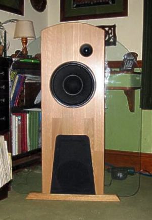
Open baffle modified to accommodate woofers.
|
|
Oh! Yes, I must get around to finishing the woofer boxes off sometime. The problem is that I just don't want to stop listening long enough to take them out of the system and up to the workshop!
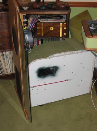
Open baffle with attached woofer. I made a gasket from half sections of foam pipe insulation to go between baffle and woofer box. The bungies are a temporary, but very effective, way of holding the two together.
|
|
Considering the woofers cost me under 100 UKP for a stereo pair including the active crossovers and amplification, I am overjoyed with their performance.
|
| Site menu
Page menu
|
|
|